Signal connector

a technology of signal connectors and connectors, applied in the direction of coupling device details, coupling device connections, electric discharge lamps, etc., can solve the problem of relatively high prime cost, achieve the effect of fewer assembling elements, easy manufacture and assembly, and break up the electrical connection

Inactive Publication Date: 2006-10-31
JOYMAX ELECTRONICS CO LTD
View PDF10 Cites 2 Cited by
  • Summary
  • Abstract
  • Description
  • Claims
  • Application Information

AI Technical Summary

Benefits of technology

[0007]Another objective of the present invention is to provide a signal connector which contains relatively fewer assembling elements and is relatively easier to manufacture and assemble. The signal connector according to the present invention concludes a hollow casing having a first hole and a second hole. An electronic connector is received in the casing and has a conductive body. The electronic connector has an end protruding out of the casing through the first hole to connect to an electronic circuit and has another end received in the casing to electrically connect to a first terminal or a second terminal. An insulation piston has a through hole to encircle the electronic connector end which protrudes out of the casing. The piston is T-like in horizontal cross-section view and has a first terminal face; and has a second terminal face in vertical cross-section view. A first terminal has an end protruding out of the casing to electrically connect to a first signal source and another end received in the casing and the first terminal has a resilient body received in the casing. The resilient body has a first resilient piece and a second resilient piece. The first resilient piece is made of conductive material and separably abuts on to the conductive body of the electronic connector to form an electrical connection therebetween. The second resilient piece so abuts on to the first terminal face that the insulation piston will not randomly move so that electrical connection between the first resilient piece and the conductive body of the electronic connector is not reversedly affected. A second terminal joint has a second terminal made of conductive material and the second terminal joint has another end to connect to a second signal source. When the second terminal joint is inserted into the casing through the second hole of the casing, the second terminal and the electronic connector are electrically connected, and the insulation piston is so pushed backward that the second terminal face of the insulation piston abuts on to the first resilient piece to push the first resilient piece away from the conductive body of the electronic connector so as to break up the electrical connection therebetween. Accordingly, the signal connector according to the present invention contains relatively fewer elements so that the manufacturing and assembling prices of it can be reduced.

Problems solved by technology

The prior art signal connector shown contain relatively more elements, thus its prime cost is relatively high.

Method used


Image

  • Signal connector
  • Signal connector
  • Signal connector

Examples


Embodiment Construction

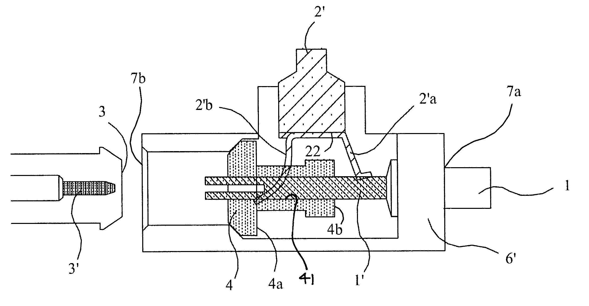
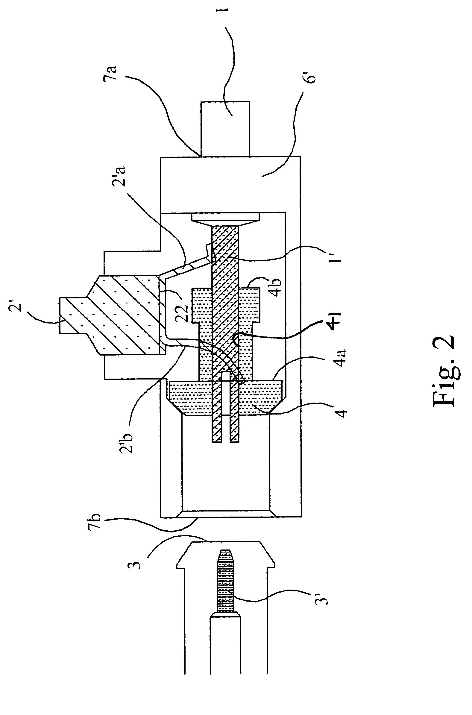
[0015]Referring to FIG. 2, the signal connector according to the present invention essentially includes a casing 6′, an electronic connector 1 having a conductive body 1′, an insulation piston 4, a first terminal 2′ having a resilient piece 22, and a second terminal joint 3 having a second terminal 3′.

[0016]The casing 6′ is a hollow casing and includes a first hole 7a and a second hole 7b.

[0017]The electronic connector 1 includes a conductive body 1′ and has one end that protrudes out of the first hole 7a of the casing 6′. Thus, the conductive body 1′ can couple to an electronic circuit of a PC board through the first hole 7a. The conductive body 1′ has another end received in the casing to electrically connect to the first terminal 2′ or the second terminal 3′.

[0018]The insulation piston 4 has a through hole 41 receiving the conductive body 1′ of the electronic connector 1 received in the casing 6′. The piston 4 is T-like in horizontal cross-section view so that the relatively big...


PUM


Abstract

A signal connector is provided according to the invention which signal connector relates to a signal connector used to connect to an electronic circuit and can be switchedly operated between two signal sources. The elements needed are simplified so that the signal connector can reduce the prime cost.

Description

BACKGROUND OF THE INVENTION[0001]1. Field of the Invention[0002]The present invention generally relates to a signal connector. Particularly, the present invention relates to a signal connector that can be switchedly operated between two signal sources and can reduce the prime cost.[0003]2. Description of Related Art[0004]Referring to FIG. 1, a prior art signal connector is shown. The prior art signal connector essentially includes a casing 6, an electronic connector 1 that includes a conductive body 1′, a first terminal 2, a metal cylinder 2a, a second terminal joint 3 that includes a second terminal 3′, an insulation piston 4 and a spring 5. The electronic connector 1 has one end protruding out of the casing 6 to couple to an electronic circuit of a PC board (not shown). The electronic connector 1 is electrically connected to the first terminal 2 or the second terminal 3′through the conductive body 1′. The spring 5 encircles the conductive body 1′ and sequentially encircles the met...

Claims


Application Information

Patent Timeline
IPC IPC(8): H01R29/00H01R9/05H01R13/703
CPCH01R13/7032
Inventor CHAN, YAT TO
Owner JOYMAX ELECTRONICS CO LTD
Why Eureka
Try Eureka