
Electric torch

a technology of electric torch and battery, which is applied in the field of electric torch, can solve the problems of changing the position relationship between the reflector and the bulb, the air tight between the terminals and the glass shell is adversely affected or even damaged, and the bulb is easy to fall o

Inactive Publication Date: 2006-10-17
KINGWELL PRODS
View PDF13 Cites 5 Cited by
  • Summary
  • Abstract
  • Description
  • Claims
  • Application Information

AI Technical Summary

Benefits of technology

"The present invention provides an electric torch that can prevent micro-splits during assembly, has a fixed bulb at the focus of a reflecting concave, and prevents the negative pole of a battery from being recessed and in poor electrical connection with the bulb. The electric torch includes a bulb holder, a head, and a body. The head has a reflector housing with an arcuate reflecting concave and a through hole for extension of the bulb. The body has an upper receiving chamber for a conductive member to electrically connect with a battery."

Problems solved by technology

However, the bulb is easy to fall off, particularly when the electric torch is fixed to a gun for shooting lighting.
However, when the electrically conductive terminal of the bulb is bent with a bending force, micro-splits may occur between the electrically conductive terminal and a glass shell of the bulb at the periphery of the terminal whereby the airtight between the terminals and the glass shell is adversely affected or even damaged.
However, the reflector is easily rotated during use, which changes the position relationship between the reflector and the bulb.
Therefore the bulb is easy to leave the focus of the reflecting concave which adversely affecting the lighting of the electric torch.
However, it is inconvenient to adjust the reflector during use.
Particularly, when the army or the police uses the electric torch for work, it is time consuming to adjust the reflector to place the bulb at the focus, which may result in losing a good chance or even danger.
Moreover, a common user cannot professionally adjust the reflector to place the bulb at the focus which reducing the lighting effect of the electric torch.
However, since the central portion of a negative pole of the battery is extremely thin, the negative pole is readily recessed due to the external force, which results in poor electrical contact between the bulb and the battery.

Method used


Image

  • Electric torch
  • Electric torch
  • Electric torch

Examples


Embodiment Construction

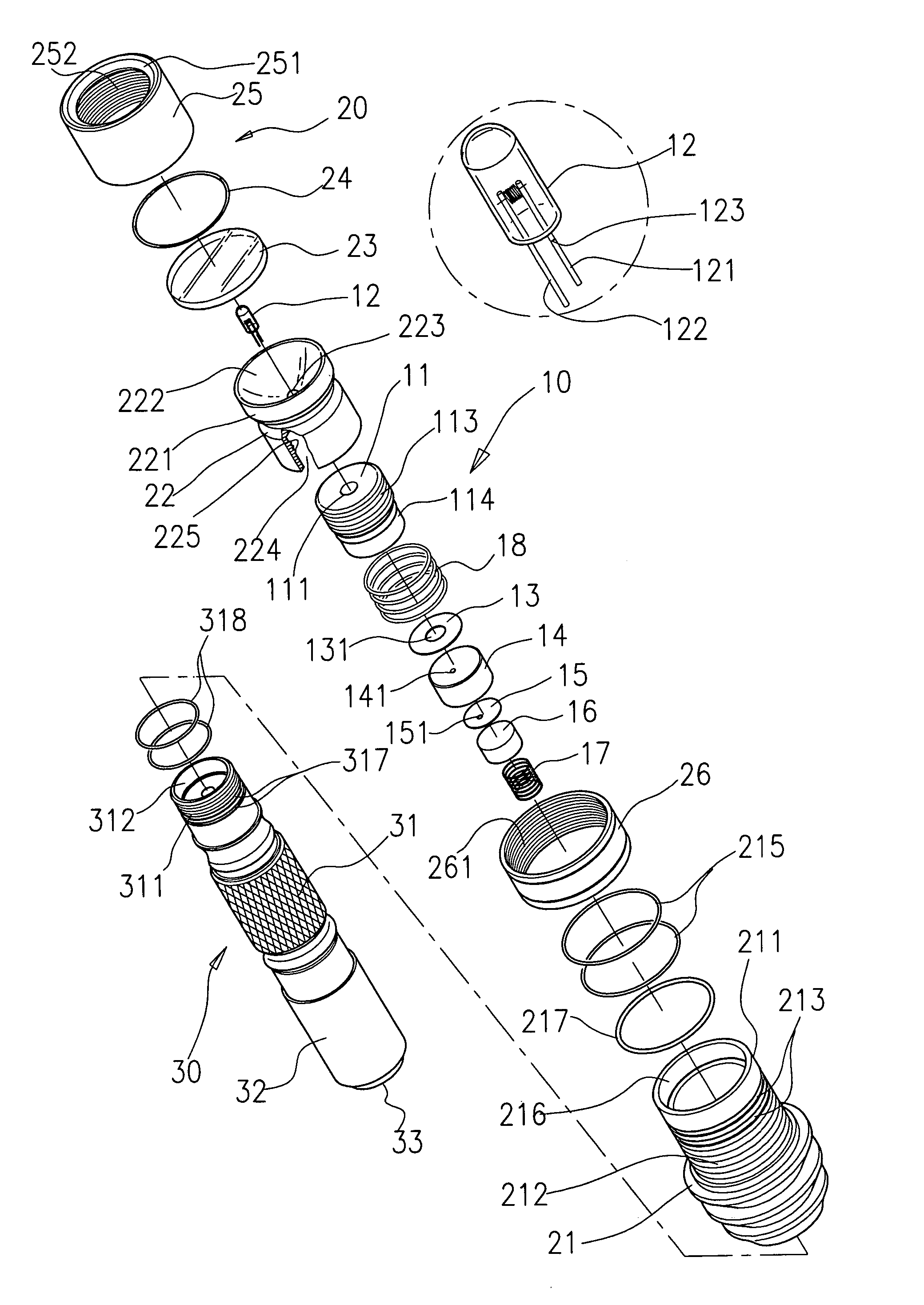
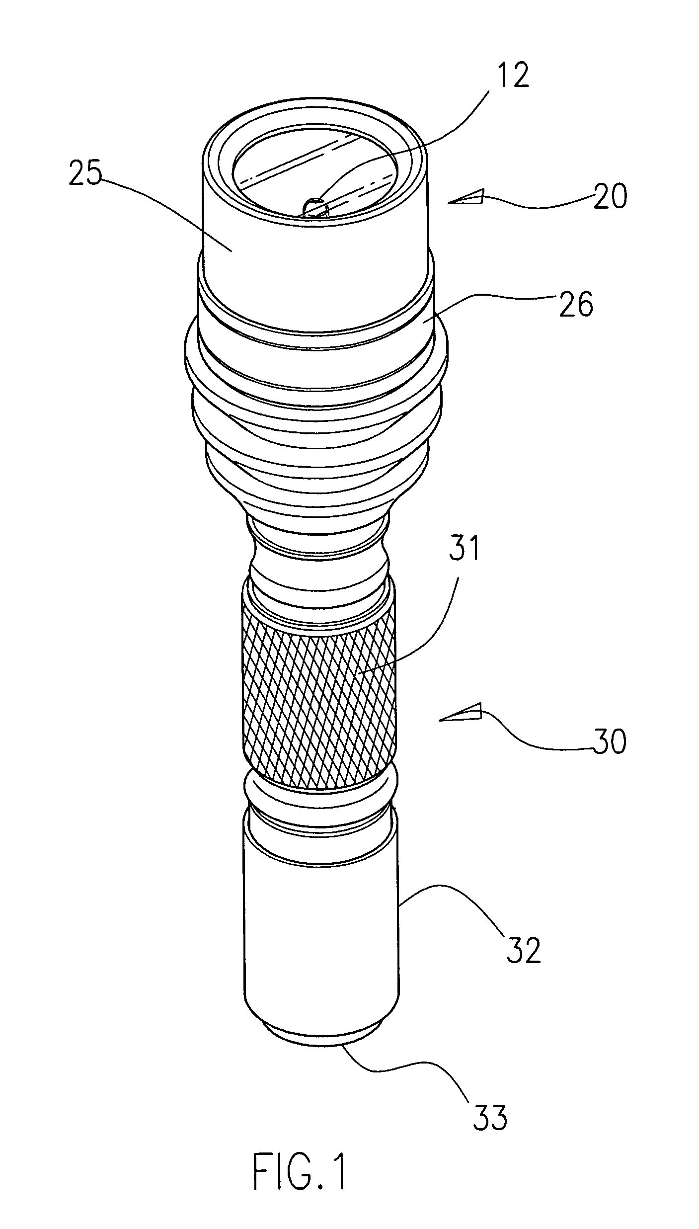
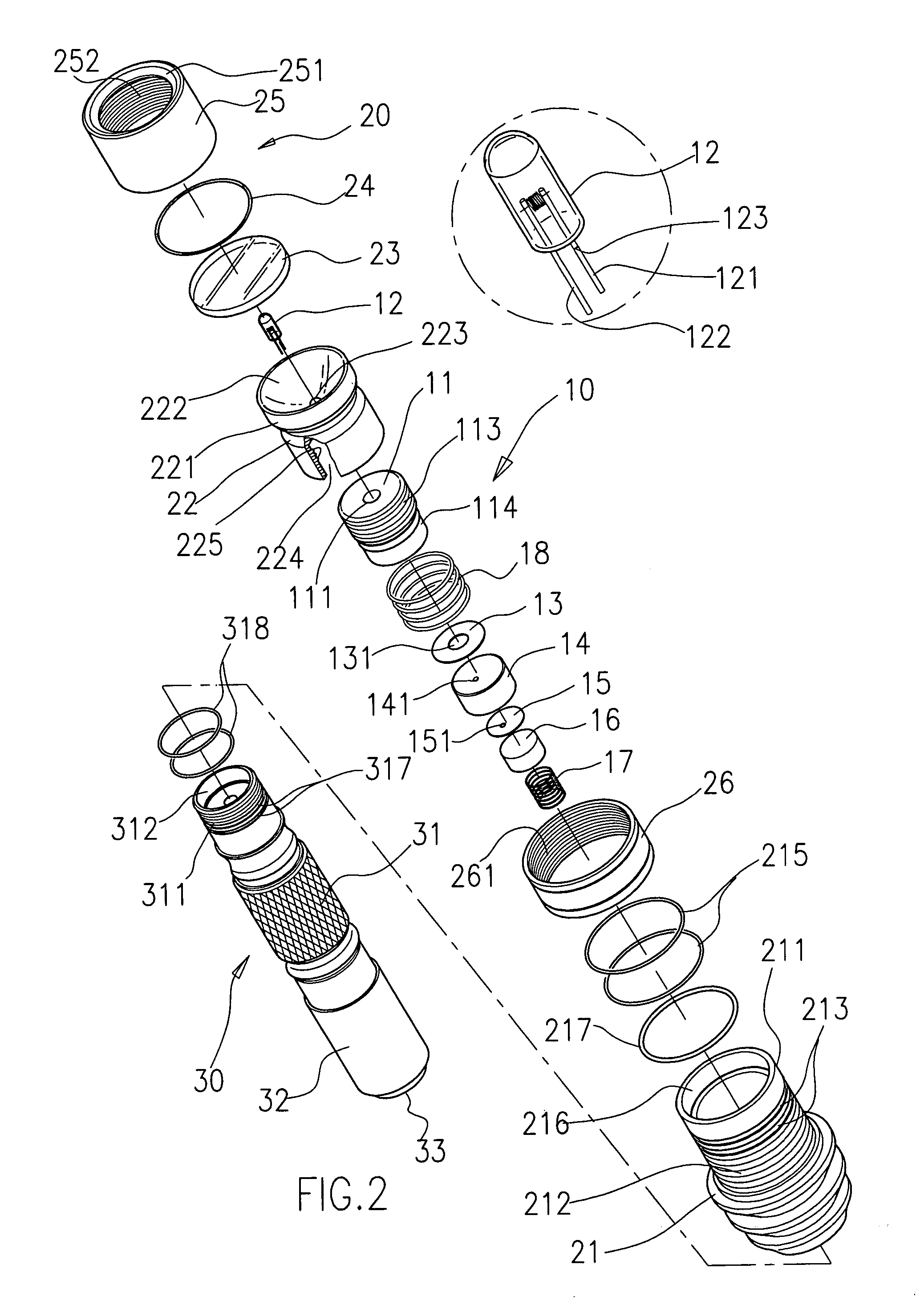
[0017]Referring to FIGS. 1–4, an electric torch of the present invention includes a bulb holder 10, a head 20 and a body 30. The bulb holder 10 includes a bulb housing 11, a bulb 12, an annular metal plate 13, an insulative sleeve 14, a conductive metal plate 15, an inner metal sleeve 16, an inner spring 17 and an outer spring 18. A bulb hole 111 and a bulb housing receiving chamber 112 in communication to the bulb hole 111 are respectively defined in the bulb housing 11 (see FIG. 4). The bulb housing 11 includes a thread segment 113 disposed at the top of the outer surface thereof and a recessed segment 114 disposed at the bottom of the outer surface thereof. The bulb 12 has two electrically conductive terminals 121, 122. A recessed portion 123 is defined in the electrically conductive terminal 121 through grinding the electrically conductive terminal 121 with a file. The recessed portion 123 is generally a triangular cutout with a bottom angle about 90 degrees. A through hole 131 ...


PUM


Abstract

An electric torch includes a bulb holder, a head and a body. The bulb holder includes a bulb housing and a bulb received in the bulb housing, with a pair of first and second electrically conductive terminals. The first electrically conductive terminal is ground by a file to form a recessed portion and the first electrically conductive terminal is easily bent at the recessed portion. The head includes a head housing with a first thread segment at the upper outside surface and the lower inside surface, a reflector housing fixed to the upper portion of the bulb housing with and an arcuate reflecting concave at the upper inside and a through hole defined in the center of the reflecting concave for extension of the bulb.

Description

BACKGROUND OF THE INVENTION[0001]1. Field of the Invention[0002]The present invention relates to an electric torch, and particularly to an electric torch which prevents a bulb thereof from adversely affecting during assembly and ensures the bulk at the focus of a reflecting concave after assembly.[0003]2. Prior Art[0004]An electric torch is one daily article for lighting. Particularly when power cut takes place in house, no power is supplied to outside at night, or the army or the police works at night, the electric torch is a necessary tool for lighting. The electric torch has a bulb which includes two electrically conductive terminals parallelly and outwardly extending from the bulb. In assembly of the electric torch, the two electrically conductive terminals are directly inserted into two metallic sockets for electrical connection. However, the bulb is easy to fall off, particularly when the electric torch is fixed to a gun for shooting lighting. To encounter the above problem, o...

Claims


Application Information

Patent Timeline
Patent Type & Authority Patents(United States)
IPC IPC(8): F21L4/00F21L4/04F21V15/01F21V31/00
CPCF21L4/005F21V15/01F21V31/00
Inventor HUANG, SHOU CHEN
Owner KINGWELL PRODS
Learn More