
Delay-locked loop (DLL) integrated circuits having binary-weighted delay chain units with built-in phase comparators that support efficient phase locking

a technology of integrated circuits and phase lockouts, which is applied in the direction of oscillation comparator circuits, pulse automatic control, multi-input and output pulse circuits, etc. it can solve the problems of inefficiency of phase lock operation, inability to know the conventional phase comparator, and relatively high degree of inefficiency in phase lock operation. to achieve the effect of convenient efficient locking of the locked loop integrated circui

Active Publication Date: 2006-10-10
INTEGRATED DEVICE TECH INC
View PDF36 Cites 91 Cited by
  • Summary
  • Abstract
  • Description
  • Claims
  • Application Information

AI Technical Summary

Benefits of technology

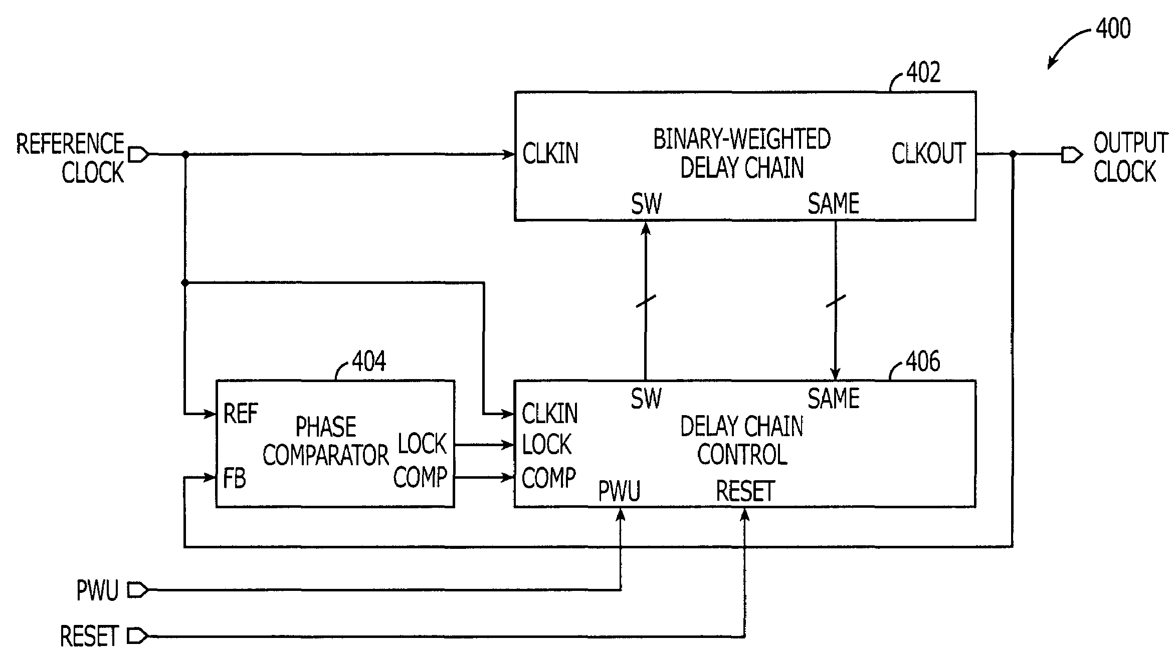
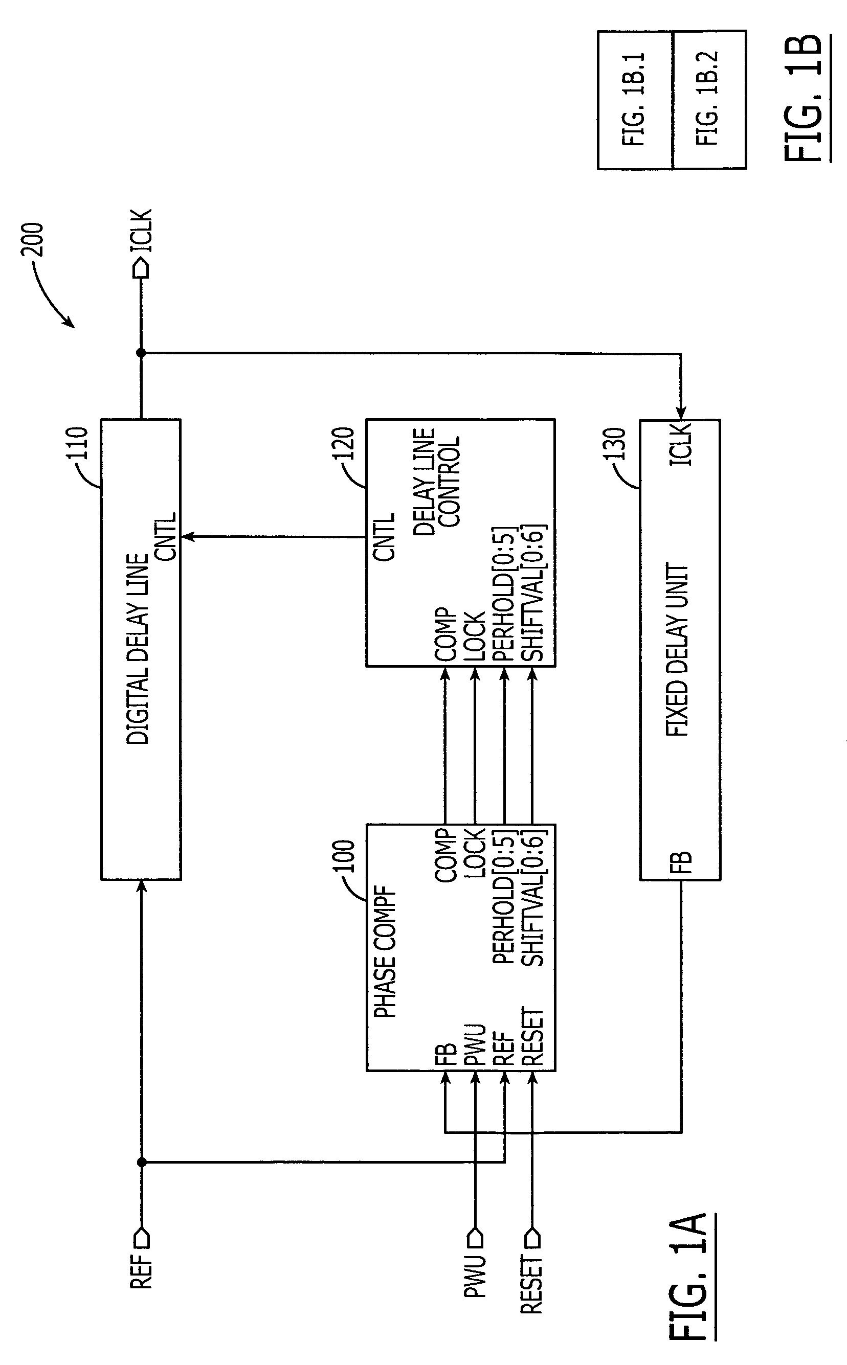
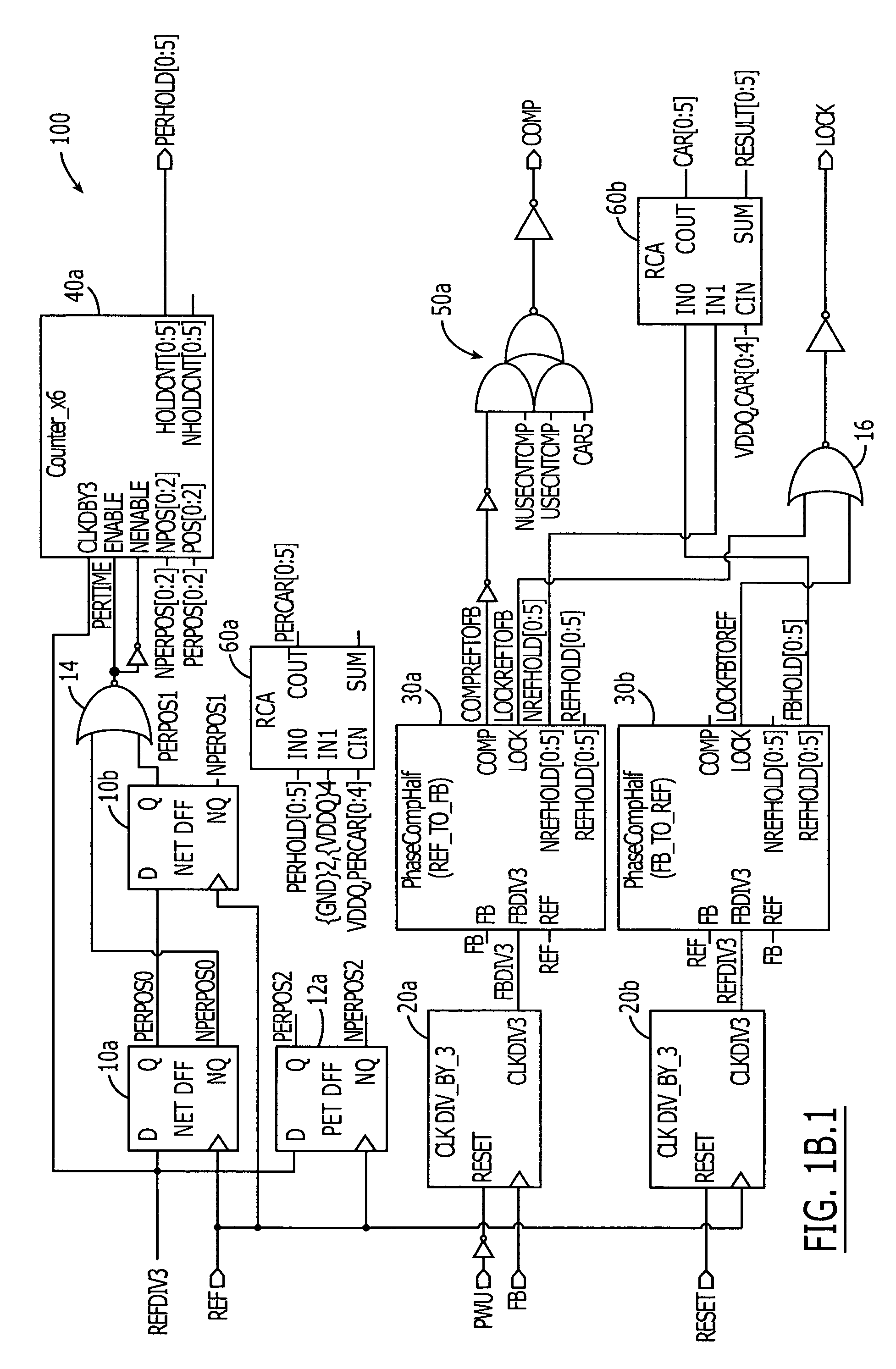
[0012]Further embodiments of the present invention include methods of operating locked loop integrated circuits. These methods may include evaluating a plurality of binary-weighted delays provided by a corresponding plurality of delay chain units within a delay chain that is responsive to a reference clock signal. This evaluating step is performed to identify a first one of the plurality of delay chain units having a first delay in excess of a fraction of a period of the reference clock signal. A step is then performed to remove at least a second one of the plurality of delay chain units having a second delay in excess of the first delay from a delay path of the delay chain. This removal step facilitates efficient locking of the locked loop integrated circuit after a power-up or reset operation. Steps may also be performed to generate a compare signal that identifies a leading or lagging phase relationship between the reference clock signal and a feedback clock signal derived from an output of the delay chain. The locked loop integrated circuit is then locked by performing a progressive binary search operation using the value of the compare signal to control adjustments to the delay of the delay chain.
[0013]Other methods of operating a locked loop integrated circuit include generating a multi-bit signal that identifies a plurality of delay chain units within a binary-weighted digital delay line that provide a delay greater than one-half a period of a reference clock signal received at an input of the digital delay line. The delay of the binary-weighted digital delay line is then set to substantially match a delay of a smallest one of the identified plurality of delay chain units. These operations may be performed to set the delay line to a mid-point delay value, which supports efficient phase locking when the locked loop integrated circuit undergoes a power-up / reset operation.

Problems solved by technology

But, when the duty cycle of the primary clock signal is not unity, operations to generate a COMP signal and achieve phase lock between the primary and secondary clock signals may be inefficient.
A potentially better alternative in this case involves speeding up the secondary clock signal by only 20% of the period of the primary clock signal, but the conventional phase comparator has no way of knowing which shift direction (slower or faster) will achieve the faster lock condition.
Furthermore, the relatively high degree of inefficiency in the phase locking operations may actually increase if a conventional binary search routine is used in place of the linear search routine.

Method used


Image

  • Delay-locked loop (DLL) integrated circuits having binary-weighted delay chain units with built-in phase comparators that support efficient phase locking
  • Delay-locked loop (DLL) integrated circuits having binary-weighted delay chain units with built-in phase comparators that support efficient phase locking
  • Delay-locked loop (DLL) integrated circuits having binary-weighted delay chain units with built-in phase comparators that support efficient phase locking

Examples


Embodiment Construction

[0027]The present invention will now be described more fully herein with reference to the accompanying drawings, in which preferred embodiments of the invention are shown. This invention may, however, be embodied in many different forms and should not be construed as being limited to the embodiments set forth herein; rather, these embodiments are provided so that this disclosure will be thorough and complete, and will fully convey the scope of the invention to those skilled in the art. Like reference numerals refer to like elements throughout and signal lines and signals thereon may be referred to by the same reference characters. Signals may also be synchronized and / or undergo minor boolean operations (e.g., inversion) without being considered different signals. The illustrated embodiments and multi-bit signals may also be scaled to handle clock signals that have lower or higher frequencies. The suffix B or prefix N to a signal name may also denote a complementary data or informati...


PUM


Abstract

Delay-locked loop integrated circuits include a delay chain having a plurality of delay chain units. The delay chain may be a binary-weighted delay chain and the delay chain units may be arranged in ascending or descending order (e.g., x1, x2, x4, x8, . . . ) according to delay. Each of the plurality of delay chain units may include a respective phase comparator. Each phase comparator is configured to identify whether a delay provided by the corresponding delay chain unit exceeds a fraction of a period of a reference clock signal applied to an input of the delay chain. This fraction of a period may be equivalent to one-half or other percentage of a period of the reference clock signal. The phase comparators with the delay chain units operate to generate a multi-bit delay value signal, which is provided to a delay chain control circuit.

Description

REFERENCE TO PRIORITY APPLICATIONS[0001]This application is a continuation-in-part (CIP) of U.S. application Ser. No. 10 / 880,804, filed Jun. 30, 2004, which claims priority to U.S. Provisional Application Ser. No. 60 / 534,318, filed Jan. 5, 2004, the disclosures of which are hereby incorporated herein by reference.FIELD OF THE INVENTION[0002]The present invention relates to integrated circuit devices and, more particularly, to delay locked loop integrated circuit devices and methods of operating same.BACKGROUND OF THE INVENTION[0003]Phase-locked loop (PLL) and delay-locked loop (DLL) integrated circuits are frequently used to generate highly accurate internal clock signals on integrated circuit substrates (e.g., chips). These PLL and DLL integrated circuits may utilize phase comparators that compare a phase of a primary clock signal, such as a reference clock signal REF, to that of a secondary clock signal, such as a feedback clock signal FB. Phase comparators may generate output sig...

Claims


Application Information

Patent Timeline
Patent Type & Authority Patents(United States)
IPC IPC(8): G01R15/12
CPCH03D13/004H03K5/26H03L7/0814H03L7/0816H03L7/085
Inventor LIN, JAMES K.
Owner INTEGRATED DEVICE TECH INC
Learn More