
Phase detector and method having hysteresis characteristics

a phase detector and hysteresis technology, applied in oscillation comparator circuits, instruments, and demodulation of angles, can solve the problems of high frequency components, serious disadvantages, and delay of clk/sub>out signal,

Inactive Publication Date: 2006-10-10
ROUND ROCK RES LLC
View PDF56 Cites 16 Cited by
  • Summary
  • Abstract
  • Description
  • Claims
  • Application Information

AI Technical Summary

Problems solved by technology

However, the CLKOUT signal may be delayed as it is coupled to the output latch.
Although the phase detector 40 can provide adequate control of the phase of the CLK signal in many instances, it has the sometimes serious disadvantage of producing a great deal of “phase jitter.” Phase jitter is a term referring to high frequency variations in the phase of a periodic signal, such as the CLKOUT signal produced by a closed-loop clock generator circuit.
For example, in a phase-lock loop phase jitter can result from high frequency components in an error signal that is produced by a phase detector and not adequately attenuated by a loop filter.
For example, using the CLKOUT signal to clock read data signals out of a memory device will cause the read data signals to have a great deal of phase jitter, thereby making it more difficult to capture the read data signals at a memory controller or other device.
This problem can be particularly severe at higher clock speeds where the period of time that data signals are valid becomes increasingly small.

Method used


Image

  • Phase detector and method having hysteresis characteristics
  • Phase detector and method having hysteresis characteristics
  • Phase detector and method having hysteresis characteristics

Examples


Embodiment Construction

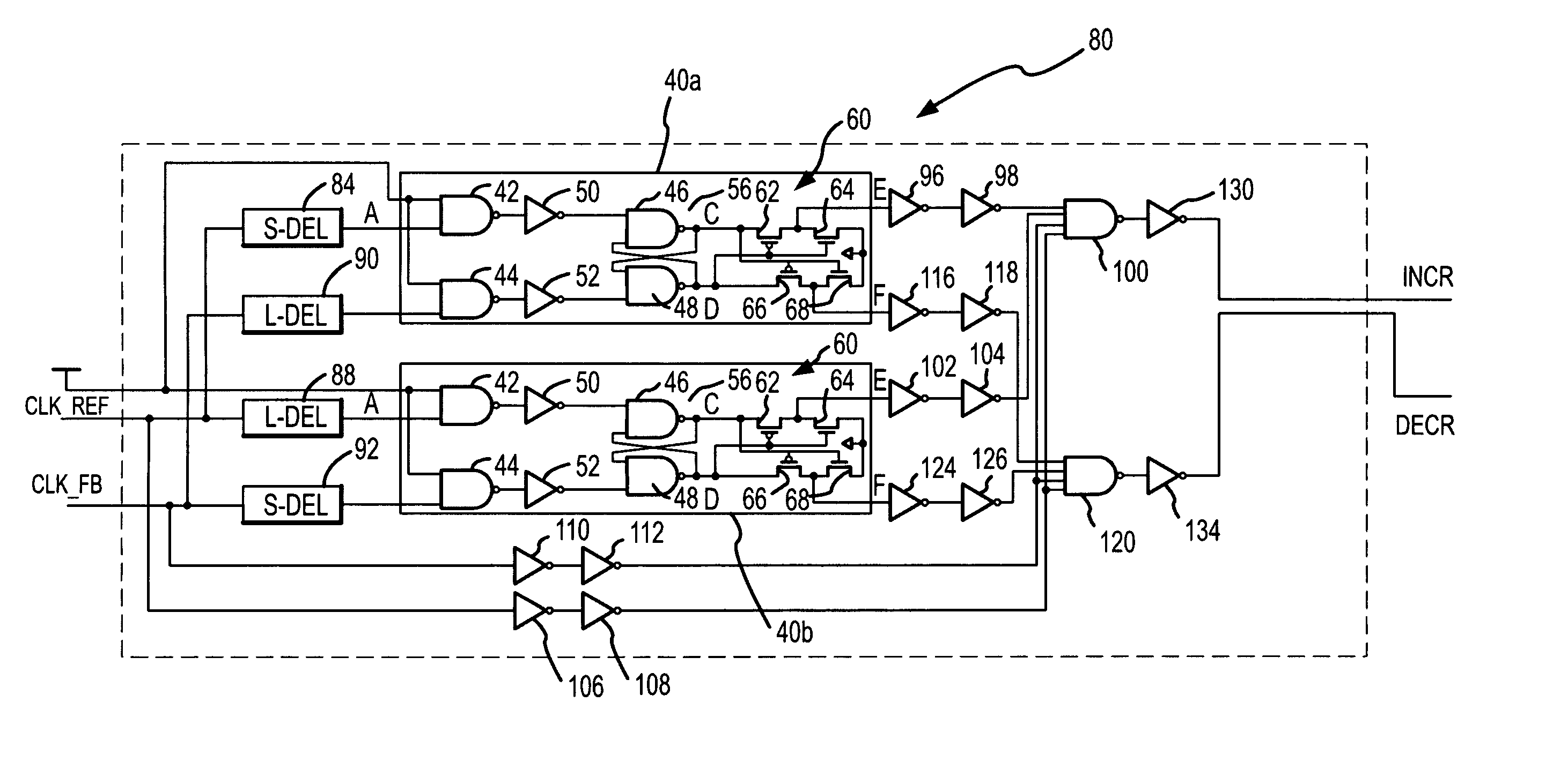
[0036]An arbiter phase detector 70 according to one embodiment of the invention is shown in FIG. 6, and the operating characteristics of the phase detector 70 are shown in FIG. 7. FIG. 7 shows various phases of the CLKFB signal in dotted limes relative to the CLKREF signal. More specifically, the CLKFB signal 72 is shown leading the CLKREF signal 74 by a first delay value DEL1, and the CLKFB signal 76 is shown lagging the CLKREF value by a second value DEL2. When the CLKFB signal leads the CLKREF signal by more than the delay value DEL1, the phase detector 70 generates an INCR signal. When the phase detector 70 is used in a delay-lock loop, phase-lock loop or other closed-loop circuit, the INCR signal causes the delay of the CLKFB signal to be increased so that the phase difference between the CLKFB signal and the CLKREF signal decreases. When the CLKFB signal lags the CLKREF signal by more than the delay value DEL2, the phase detector 70 generates a DECR signal. The DECR signal cau...


PUM


Abstract

A phase detector generates a first output signal if a feedback clock signal leads a reference clock signal by more than a first time. The phase detector generates a second output signal if the feedback clock signal lags the reference clock signal by more than a second time. If the feedback clock signal either leads the reference clock signal by less than the first time or lags the reference clock signal by less than the second time, neither output signal is generated. The phase detector may be used in a delay-lock loop in which the first and second output signals increase or decrease a delay of the reference clock signal by respective first and second delay increments. In such case, the each of the first and second delay increments should be less than the sum of the first and second times.

Description

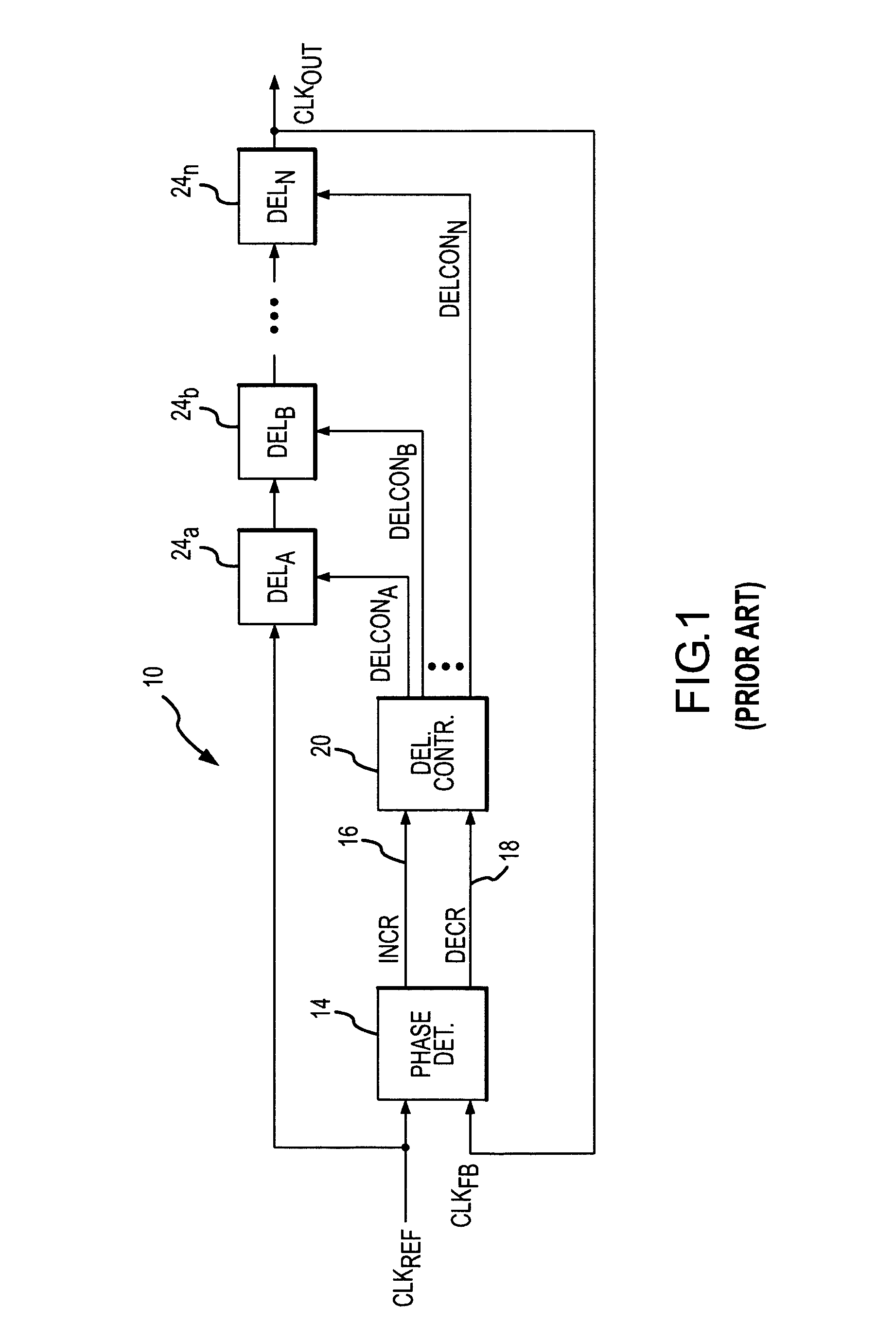
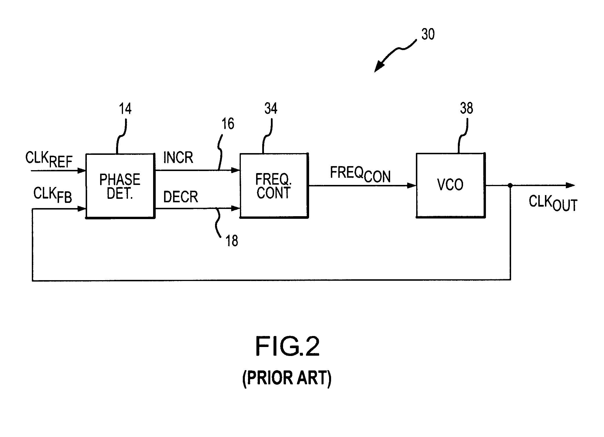
TECHNICAL FIELD[0001]This invention relates to closed-loop clock generating devices and methods, and, more particularly, to a phase detector for use in a delay-lock loop that may be advantageously used in a memory device.BACKGROUND OF THE INVENTION[0002]Phase detectors, which determine the difference in phase between two signals, are used in a variety of circuits. A common use for phase detectors is in closed loop clock generator circuits, such as phase-lock loops and delay-lock loops. A typical delay-lock loop 10 is shown in FIG. 1. The delay-lock loop 10 includes a phase detector 14 that receives a reference clock signal CLKREF and a feedback clock signal CLKFB. As explained in greater detail below, the CLKFB signal is derived from a signal generated at the output of the delay-lock loop 10. The delay-lock loop 10 delays the CLKREF signal to produce the output signal by a delay that causes the CLKREF and CLKFB signals to have substantially the same phase.[0003]The phase detector 14...

Claims


Application Information

Patent Timeline
Patent Type & Authority Patents(United States)
IPC IPC(8): G01R25/00H03D3/00H03D13/00
CPCH03D13/004
Inventor JOHNSON, GARYLI, WEN
Owner ROUND ROCK RES LLC
Learn More