
Intelligent switch for connecting power to a load

a technology of intelligent switch and load, applied in the direction of discharge tube/lamp details, emergency protective circuit arrangement, process and machine control, etc., can solve problems such as power was

Inactive Publication Date: 2006-10-10
AZOTEQ PTY LTD
View PDF138 Cites 46 Cited by
  • Summary
  • Abstract
  • Description
  • Claims
  • Application Information

AI Technical Summary

Benefits of technology

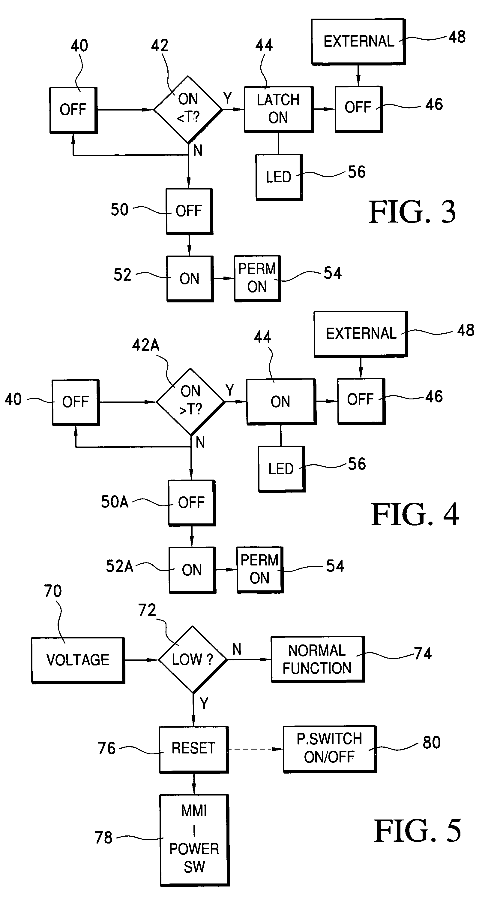
[0027]After the circuit has been powered up or down the memory unit may be reset with a fresh measurement of the prevailing open circuit voltage or of the closed circuit voltage of the power source. The control circuit may be adapted to close the power switch automatically and for a short period of time for obtaining a closed circuit voltage measurement of the power source. This can be done for example once every 24 hours.

Problems solved by technology

This approach is wasteful of power.

Method used


Image

  • Intelligent switch for connecting power to a load
  • Intelligent switch for connecting power to a load
  • Intelligent switch for connecting power to a load

Examples


Embodiment Construction

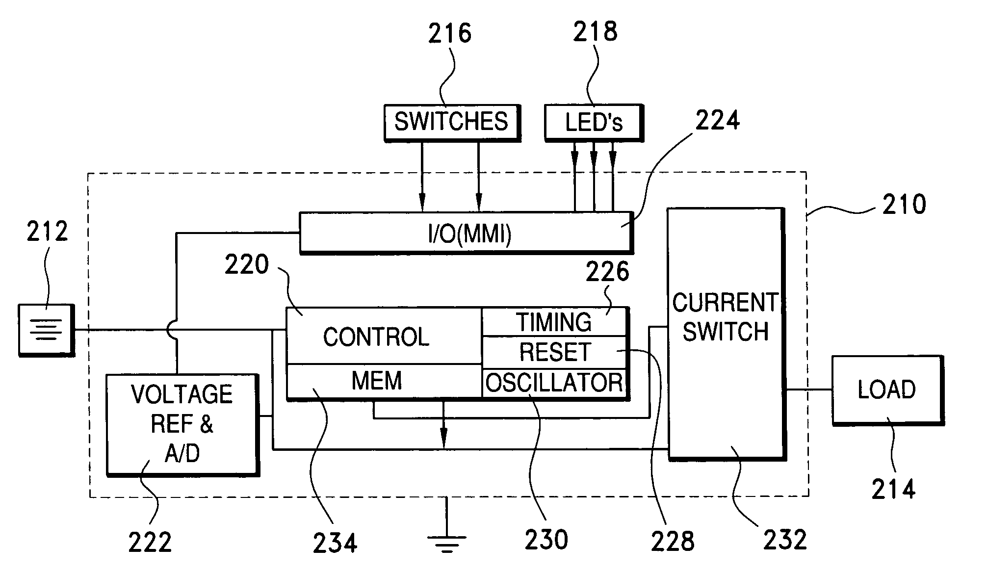
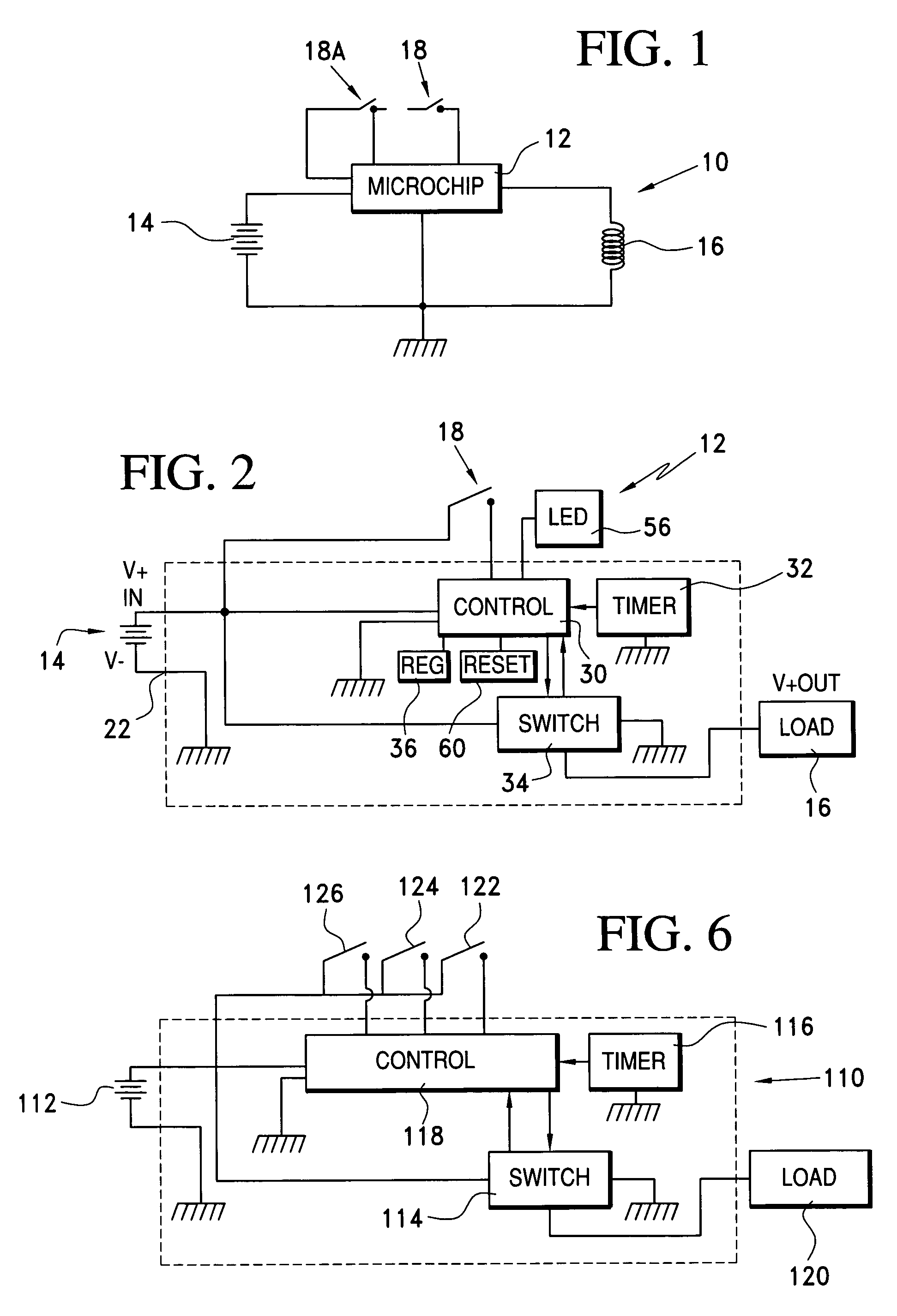
[0050]FIG. 1 of the accompanying drawings schematically illustrates a switching circuit 10 which includes a microchip or control circuit 12, a battery 14, a load 16, and a signal switch 18.

[0051]The arrangement shown in FIG. 1 is similar to what has been described in the specification of international application No. PCT / ZA99 / 00107 and, for a detailed description of the operation of the arrangement, reference is made to the specification of the international application.

[0052]The switch 18 functions as an interface between an operator or any appropriate actuating mechanism, and the control circuit 12, and hence is referred to as a man-machine-interface (MMI) This term is however adopted merely for the sake of convenience for, as noted, the switch could be operated by human intervention or by any mechanism eg. a closing door or other device which acts on the switch. The control circuit 12, in response to signals input from the MMI, causes power to be applied from the battery 14 to th...


PUM


Abstract

A switching circuit includes a microchip which, in response to a signal from a signal switch, controls the operation of a power switch which, when closed, connects a load to a battery. The microchip can monitor the status of the battery and control the power switch to ensure optimum operation of the load and optimum usage of the energy in the battery. The microchip can control the connection of the load to the battery in different ways according to the manner of operation of the signal switch.

Description

CROSS REFERENCE TO RELATED APPLICATIONS[0001]This application is a national phase filing under 35 U.S.C. 371 of International Application No. PCT / ZA01 / 00081, file Jun. 13, 2001.BACKGROUND OF THE INVENTION[0002]The invention relates generally to an intelligent switch which is suitable for controlling the use of a battery driven device such as a flashlight, toy, motor or the like and, more particularly, is concerned with an intelligent electrical device of the kind described in the applicant's international application No. PCT / ZA99 / 00107.[0003]In the PCT application mechanical switches function as a man-machine-interface (“MMI”) between the device and an operator. The MMI functions are controlled by very low current signals using touch pads, carbon coated membrane type switches or similar mechanisms. A microchip is responsive to input signals from the MMI and can, according to application, be used in various ways. For example with a flashlight the MMI may control the on / off operation ...

Claims


Application Information

Patent Timeline
Patent Type & Authority Patents(United States)
IPC IPC(8): H01H3/26H02H3/00H01J7/24H02J7/00H02M3/157
CPCH02J7/0047H02J7/0063H02M3/157H02J2007/0095H02J2207/10H02J7/0048H02J7/007182
Inventor BRUWER, FREDERICK JOHANNESAUCAMP, BRANDTGREYLING, ABRAHAM CARL
Owner AZOTEQ PTY LTD
Learn More