Optical disc apparatus

a technology of optical discs and optical discs, applied in the direction of data recording, disposition/mounting of heads, instruments, etc., can solve the problems of optical disc data sometimes being reproduced erroneously, the lens holder cannot move smoothly,

Inactive Publication Date: 2006-09-26
FUNAI ELECTRIC CO LTD
View PDF9 Cites 1 Cited by
  • Summary
  • Abstract
  • Description
  • Claims
  • Application Information

AI Technical Summary

Benefits of technology

[0014]An object of the present invention is to provide an optical disc apparatus by which sticking of the objective lens held on the lens holder due to the adhesion of dust or the like can be eliminated, and errors in the focusing operation and the tracking operation can be reduced.
[0020]By such a configuration, the objective lens held on the lens holder is dynamically moved by the focusing coil andlor the tracking coil prior to be moved for focusing the light beam on the data recording face of the optical disc. Thus, sticking of the objective lens held on the lens holder due to adhesion of dust, break or deformation of components can be removed, so that the objective lens can be moved smoothly for focusing and tracking the light beams on the data recording track on the data recording face of the optical disc. As a result, the data can be recorded or reproduced from the optical disc stably.

Problems solved by technology

In the above-mentioned conventional optical discs, the lens holder cannot move smoothly due to sticking of the lens holder when dust is adhered in a gap between the lens holder and the sliding shaft.
In such the case, the data are sometimes reproduced erroneously from the optical disc due to unsmooth movements of the focusing operation and the tracking operations.

Method used


Image

  • Optical disc apparatus
  • Optical disc apparatus
  • Optical disc apparatus

Examples


Embodiment Construction

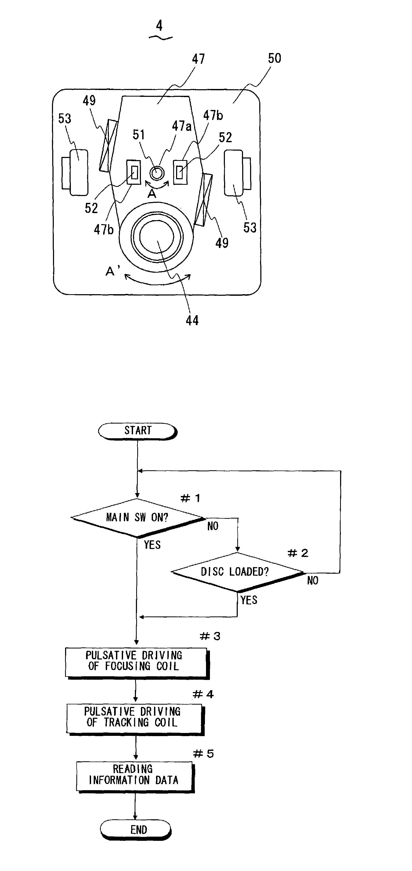
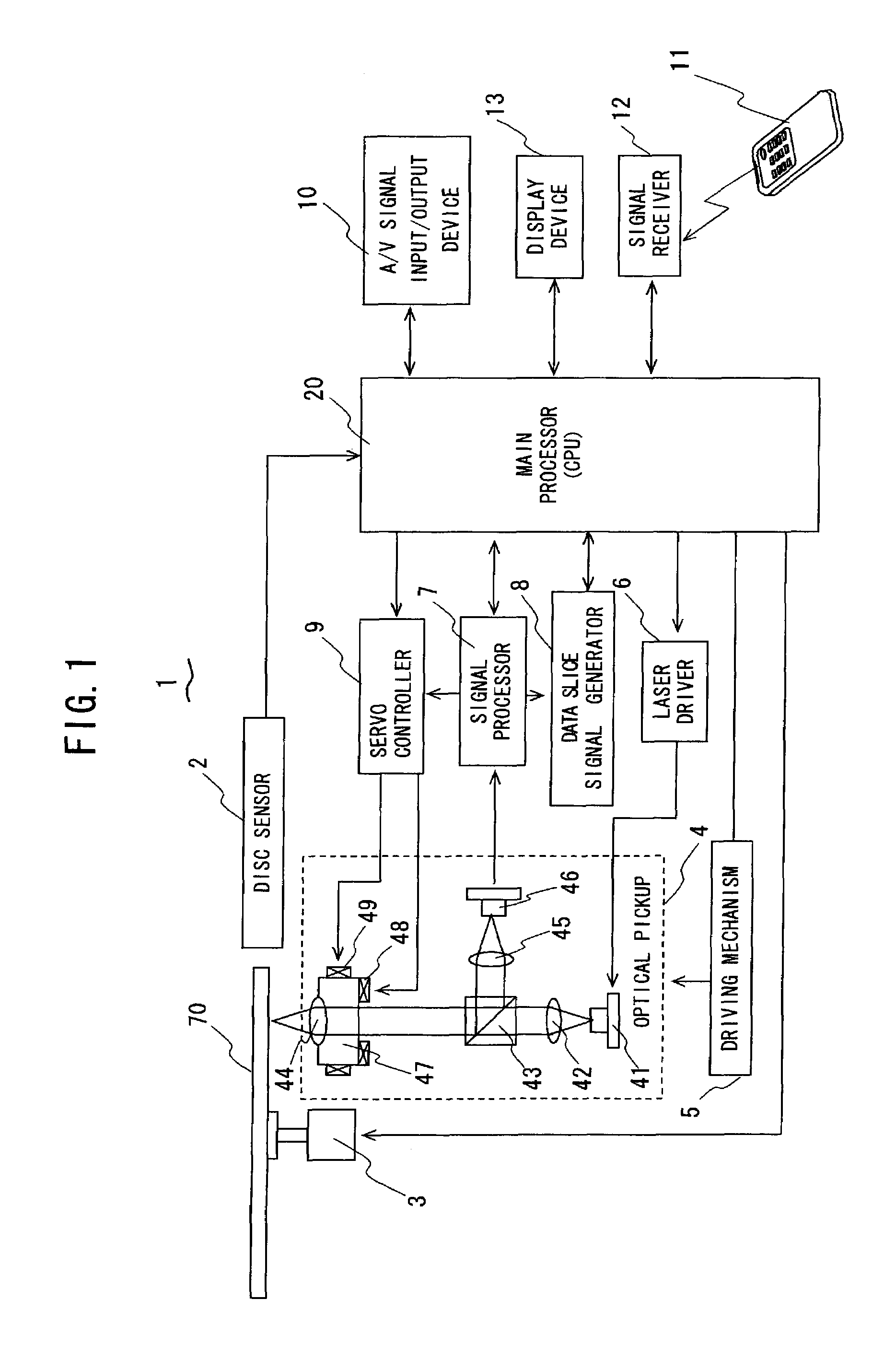
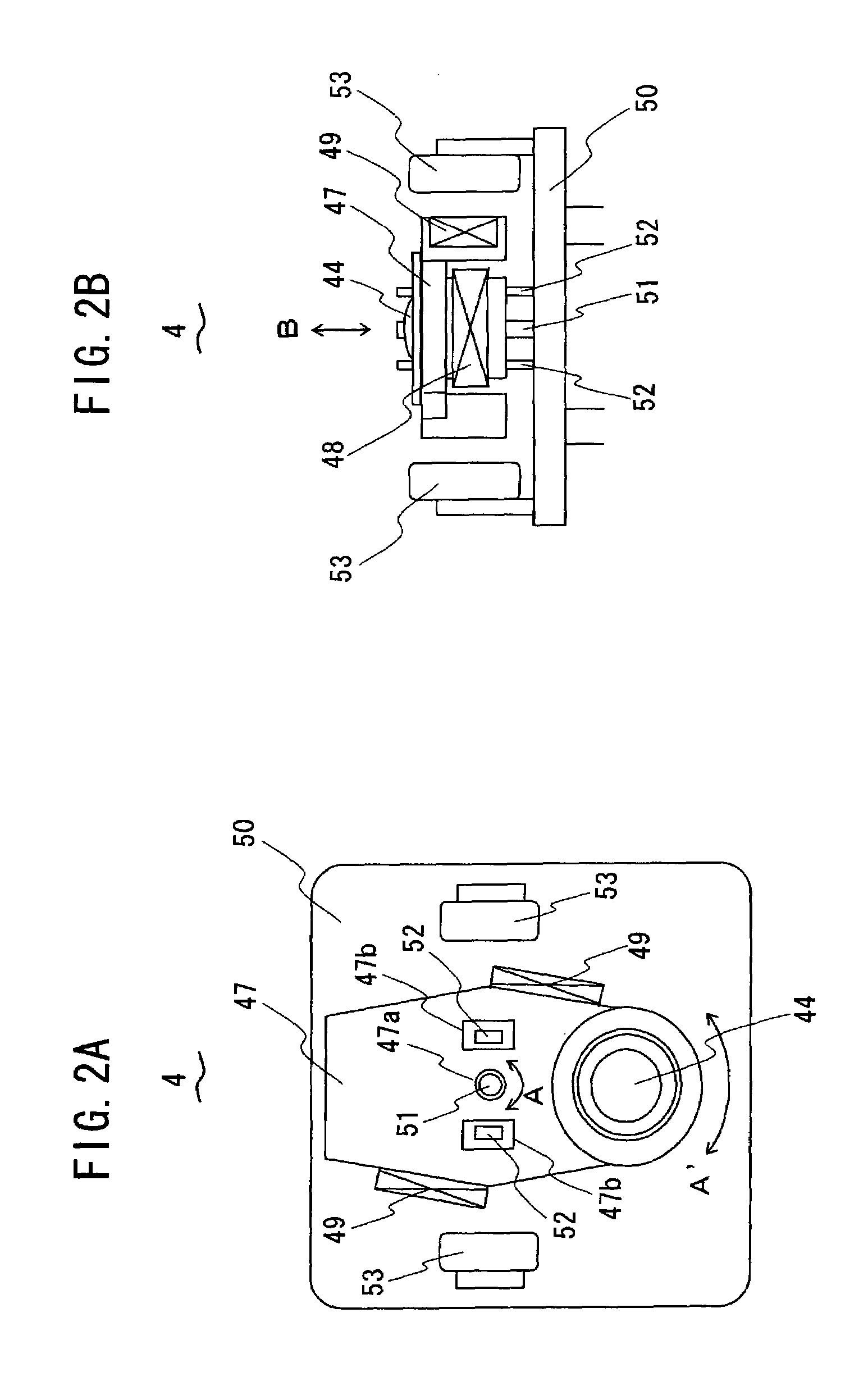
[0028]An embodiment of an optical disc apparatus in accordance with the present invention is described. FIG. 1 is a block diagram showing a configuration of the optical disc apparatus in the embodiment. The optical disc apparatus 1 records and / or reproduces data such as sounds or video images on an optical disc 70 such as a CD or a DVD on which data recording tracks are formed concentrically or spirally.

[0029]The optical disc apparatus 1 comprises a disc sensor 2, a spindle motor 3, an optical pickup 4, a driving mechanism 5, a laser driver 6, a signal processor 7, a data slice signal generator 8, and a servo controller 9. The servo controller 9 serves as not only a focusing servo controller but also a tracking servo controller. The optical disc apparatus 10 further comprises an audio / visual (A / V) signal input / output device 10, a remote controller 11, a signal receiver 12, a display device 13 and a main processor 20 constituted by, for example, a ROM for memorizing an operation prog...


PUM

PropertyMeasurementUnit
angleaaaaaaaaaa
voltagesaaaaaaaaaa
areaaaaaaaaaaa

Abstract

In an optical disc apparatus for recording and / or reproducing data on an optical disc, a lens holder for holding an objective lens is dynamically moved not only in a direction perpendicular to a data recording face of an optical disc but also in a direction parallel to the data recording face and crossing substantially at right angle with data recording tracks on the data recording face when the optical disc is loaded on the optical disc apparatus so as to remove the sticking of the movement of the objective lens due to adhesion of dust, break or deformation of the components.

Description

BACKGROUND OF THE INVENTION[0001]1. Field of the Invention[0002]The present invention relates to an optical disc apparatus for recording and / or reproducing data on an optical disc such as a CD (compact disc) or a DVD (digital versatile disc).[0003]2. Description of the Related Art[0004]In the optical disc apparatus, data are reproduced from the optical disc such as the CD or DVD, and the data are recorded on recordable optical disc such as a CD-R, CD-RW, DVD-R, DVD-RW, or the like by an optical head called “optical pickup”. Data recording tracks are formed concentrically or spirally on such the optical disc. The optical pickup is constituted for emitting light beams such as laser beams by a laser diode, for focusing the light beams on the data recording face of the optical disc through an objective lens, for receiving a reflected light reflected from a data recording face of the optical disc and converting variation of intensity of the reflected light to electric signals by a photo-...

Claims


Application Information

Patent Timeline
Patent Type & Authority Patents(United States)
IPC IPC(8): G11B7/00G11B7/085G11B7/09
CPCG11B7/0945
Inventor KUWAYAMA, YASUNORIFUKUI, TOSHIAKI
Owner FUNAI ELECTRIC CO LTD
Why Eureka
Try Eureka