
Multi-element biased suture clip

a suture clip and multi-element technology, applied in the direction of suture equipment, snap fasteners, buckles, etc., can solve the problems of increasing so as to achieve the effect of minimizing or eliminating the difficulty of knot tying

Active Publication Date: 2006-09-19
ABBOTT LAB INC
View PDF97 Cites 108 Cited by
  • Summary
  • Abstract
  • Description
  • Claims
  • Application Information

AI Technical Summary

Benefits of technology

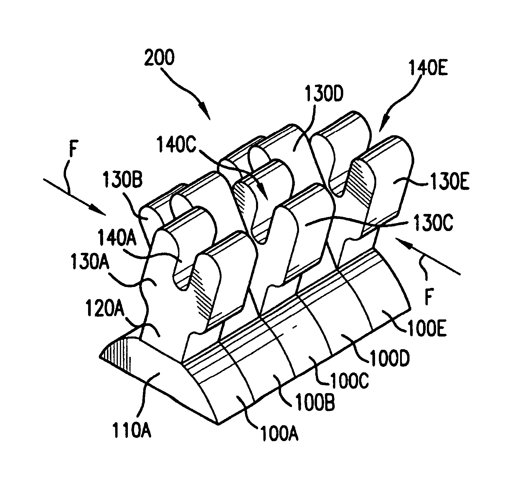
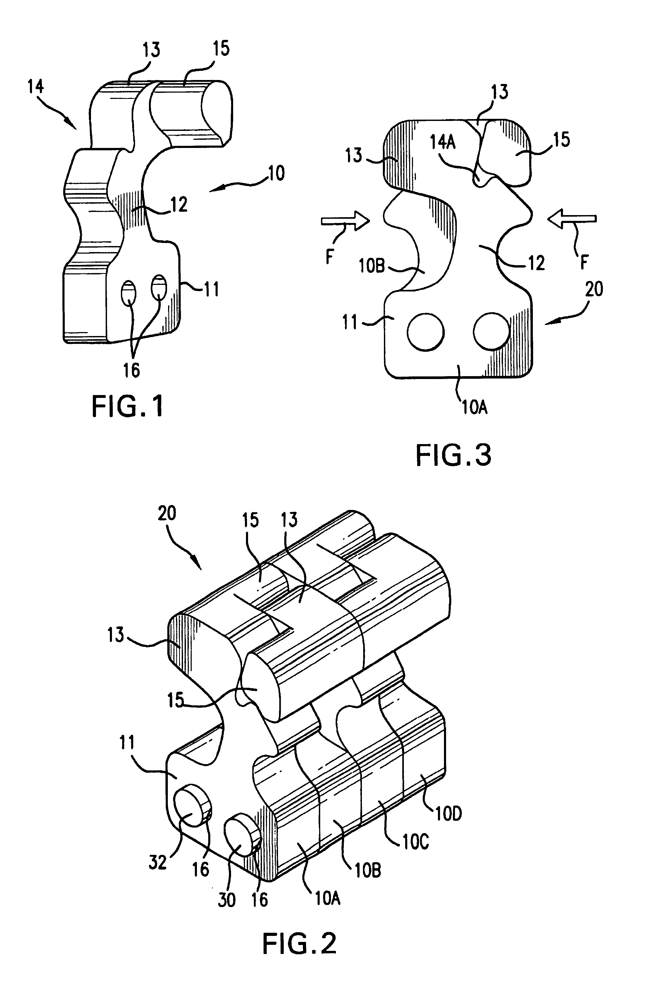
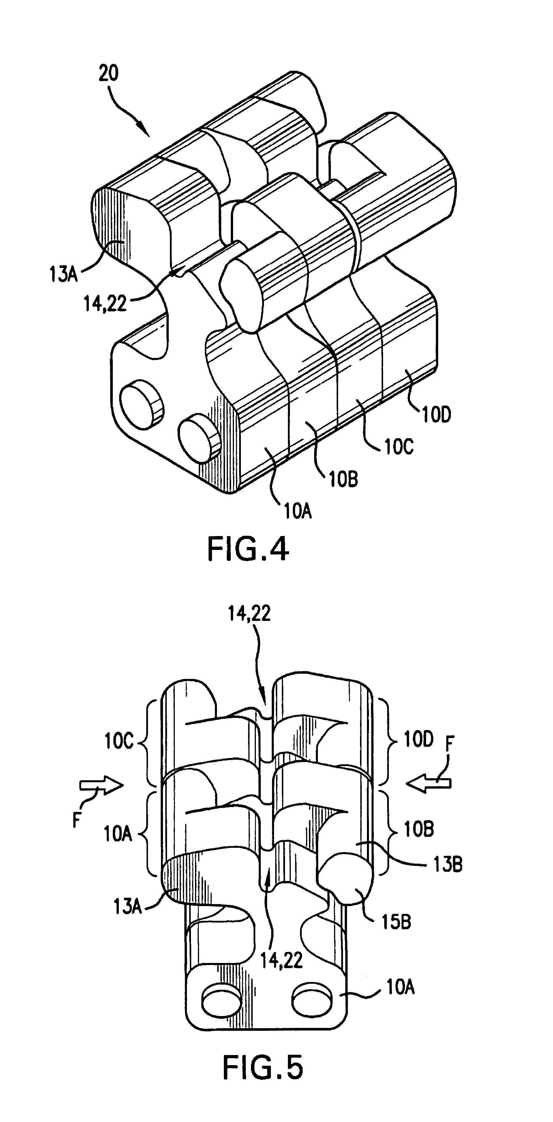
[0007]Still other embodiments may also include a biasing / positioning device which is used to bias and hold the row of elements in the first position (at which time an opening is defined along the top of the row for receipt of the suture length or suture pair therein). Preferably, the biasing device is slidably received around the row of elements such that as the biasing force is removed, (e.g.: as the row of elements are slidably pushed or otherwise advanced through the biasing device), the elements then move to a non-biased position (at which time a tortuous path is formed along through the row of elements). Thus, a suture pair can effectively be clamped or “fastened” together when the sutures are held in such a tortuous path. Features of the present invention allow a physician to completely avoid manual suture knot tying. Therefore, the bulky multiple loops or “throws” required when knot tying can be minimized or eliminated. Instead, the suture pair is simply “clamped” or held together between the flexible elements.
[0008]Alternatively, the present system can be clamped onto a single suture and can thus act as an anchor preventing movement of a tissue layer along a single suture strand. Specifically, when using only a single strand of suture, the suture is clamped so that it does not move with respect to the clamping system.

Problems solved by technology

There are a number of disadvantages of knotting sutures together to secure tissues to one another.
For example, manual knot tying requires considerable dexterity.
Also, manual knot tying can take considerable time.
Knot tying is further complicated by the fact that surgical sutures have low friction surfaces.
This multiple-throw problem occurs even if an automatic knot tying device is used.
Unfortunately, as the number of loops or “throws” incorporated into the knot increase, the knot becomes increasingly large and bulky.
Thus, manual knot tying requires considerable space both in which to view, and to perform, the actual suture knot tying.
Therefore, knot tying is particularly difficult in areas of limited available space or access, such as, for example, at the back of the patient's heart during a coronary artery bypass graft (CABG) operation, or at the artery in the tissue tract after a femoral artery catheterization procedure.

Method used


Image

  • Multi-element biased suture clip
  • Multi-element biased suture clip
  • Multi-element biased suture clip

Examples


Embodiment Construction

[0034]In accordance with the present invention, a suture clamping system is provided. In preferred aspects, the suture clamping system comprises a plurality of individual flexible elements positioned together in a row. In various preferred embodiments, the individual flexible elements are shaped the same. Optionally, the row of elements is formed by positioning successive identically shaped elements adjacent to one another. It is to be understood, however, that the individual elements in the row need not be identical in shape to one another. It is also to be understood that the individual elements need not be positioned in direct “touching” contact side-by-side with one another, but may instead be positioned some distance apart from one another. As will also be explained, various embodiments of the invention may include rows of elements including both flexible and non-flexible elements. In fact, in one embodiment, only one flexible element is required.

[0035]One or more of these elem...


PUM


Abstract

A suture clamping system, including a plurality of elements positioned together in a row, wherein at least one of the elements is flexible, the plurality of elements each being dimensioned such that an opening slot is formed through the row of elements when the at least one flexible element is biased into a first position, and wherein a tortuous path is formed through the row of elements when the elements are not biased. A method of clamping a suture pair, including biasing a row of adjacent flexible elements to a first position in which an opening slot is formed therealong; receiving the suture pair into the opening slot; and removing the biasing such that the adjacent flexible elements move to positions which hold the suture pair in a tortuous path.

Description

TECHNICAL FIELD[0001]The present invention relates to systems for securing a pair of suture lengths together or for using a single strand of suture to secure tissues together at an operative site in a patient without necessarily tying a knot.BACKGROUND OF THE INVENTION[0002]Sutures are used to sew tissue together, and thereby close tissue openings, cuts or incisions during or after any of a very wide variety of medical procedures. Typically, the surgeon manually ties together a suture pair to close the opening, however, automatic suture tying systems have also been developed.[0003]There are a number of disadvantages of knotting sutures together to secure tissues to one another. For example, manual knot tying requires considerable dexterity. Also, manual knot tying can take considerable time. Knot tying is further complicated by the fact that surgical sutures have low friction surfaces. Therefore, it is typically necessary for a surgeon to include many “throws” when tying the knot. T...

Claims


Application Information

Patent Timeline
IPC IPC(8): A61B17/04
CPCA61B17/0487A61B2017/0454Y10T24/202Y10T24/3936Y10T24/3929A61B2017/0488
Inventor ANDERSON, STEVEN C.
Owner ABBOTT LAB INC
Learn More