
Magnetic transmission

a transmission and magnetoelectric technology, applied in the direction of dynamo-electric brake control, dynamo-electric machines, control systems, etc., can solve the problems of mechanical gears that can generate much vibration and noise during operation, mechanical gears that need lubrication and inspection, and all the problems caused by friction, wear, vibration and noise disappear

Active Publication Date: 2006-09-12
NISSEN EDWARD WILLIAM
View PDF4 Cites 77 Cited by
  • Summary
  • Abstract
  • Description
  • Claims
  • Application Information

AI Technical Summary

Benefits of technology

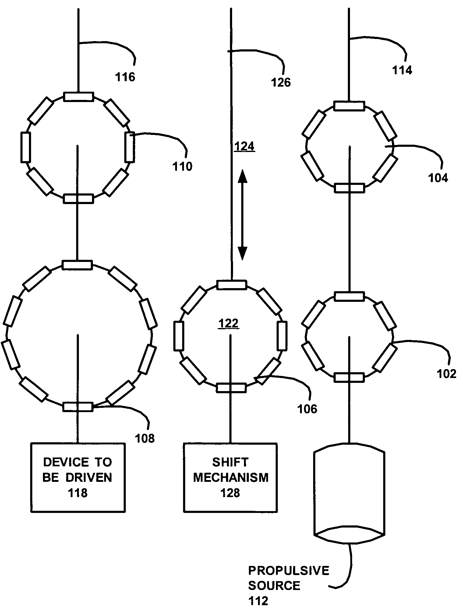
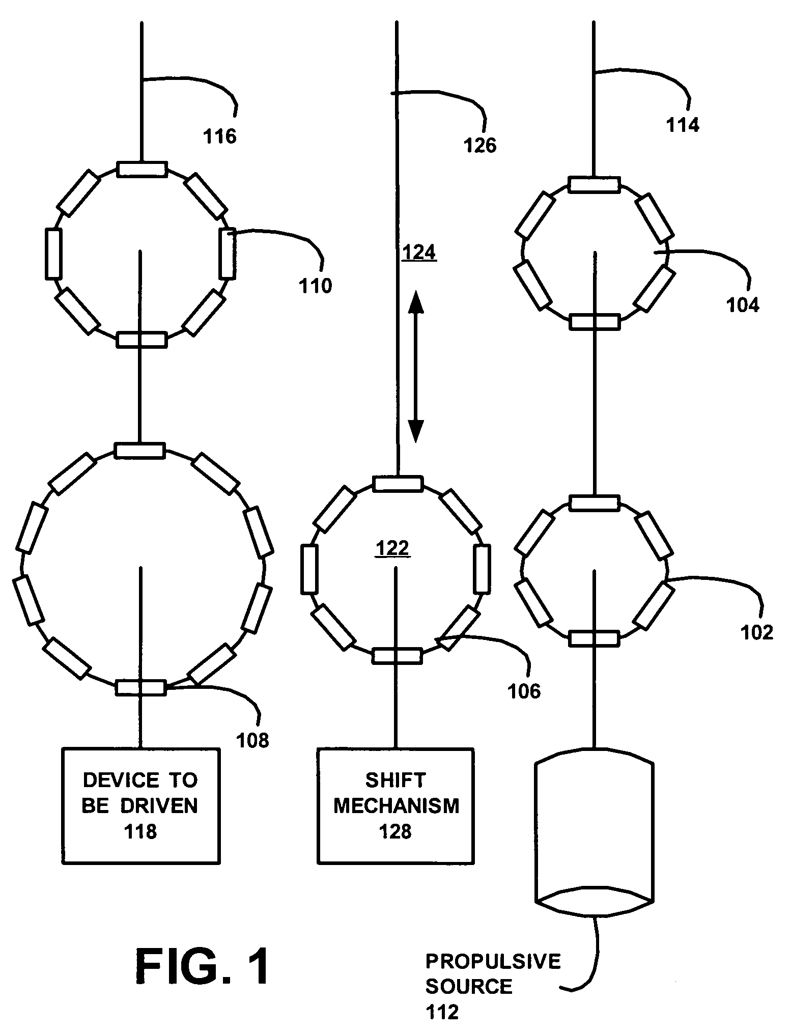
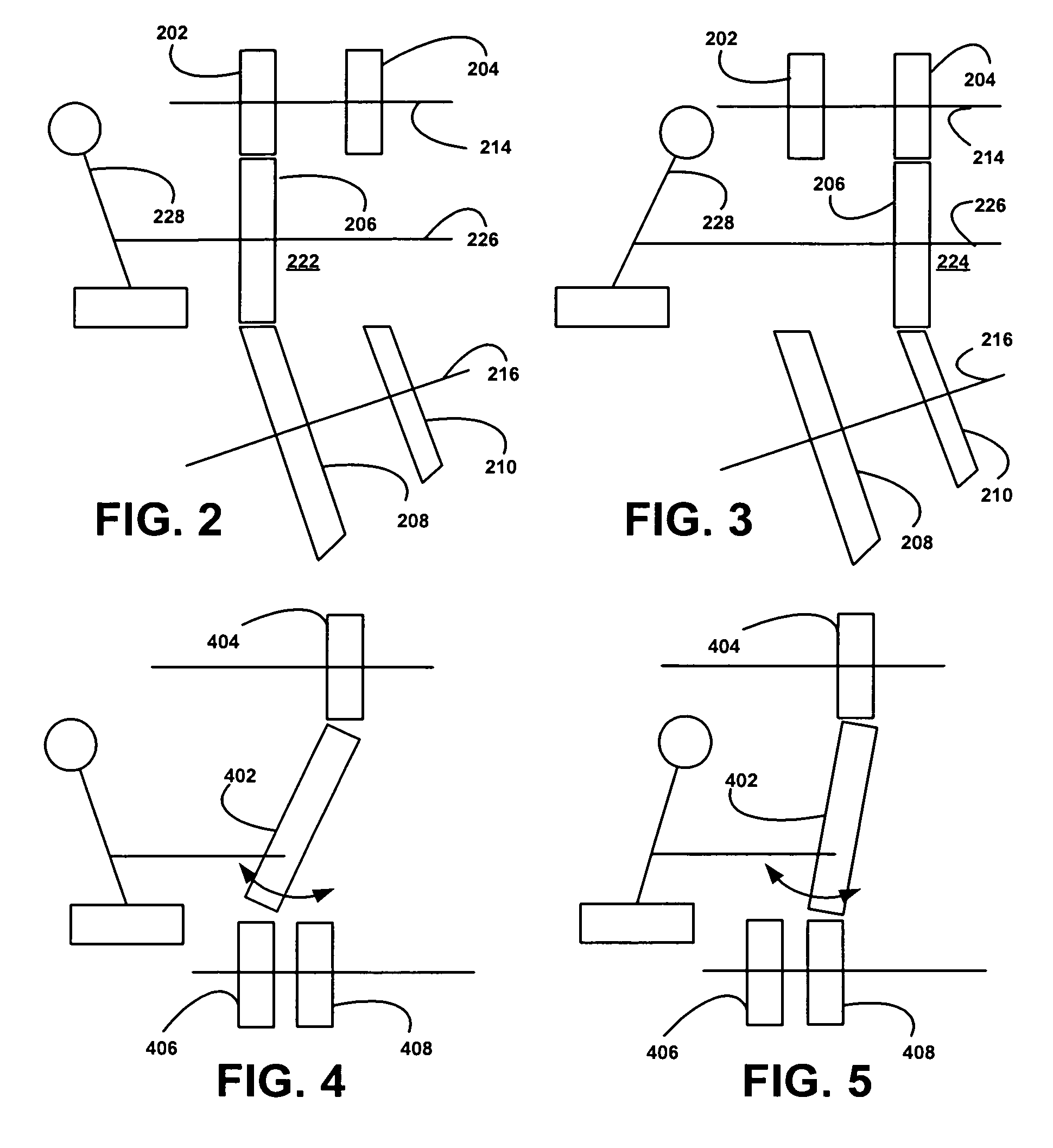
"The present invention is a magnetic transmission apparatus that has multiple gear trains. Some of the gears are non-coaxial, meaning they are not all in the same line. One of these non-coaxial gears can move relative to the others to create the gear trains. This design allows for smoother shifting of gears and improved performance of the apparatus."

Problems solved by technology

For example, mechanical gears can generate much vibration and noise during operation, whereas magnetic gears significantly reduce such vibration and noise.
Furthermore, the mechanical gears need lubrication and inspection for wear and tear from time to time.
Therefore, if the gears can operate in a non-contact fashion, all those problems caused by friction, wear, vibration and noise disappear.
Because the magnetic coupling is achieved by the action of an electromagnet, problems, such as winding space and control current, must also be considered.
Therefore, this type of magnetic gear design becomes rather complicated.
However, due to directional restrictions of a coaxial type of magnetic gear transmission system, non-coaxial type of magnetic gear transmission system cannot be completely replaced with the coaxial type.

Method used


Image

  • Magnetic transmission
  • Magnetic transmission
  • Magnetic transmission

Examples


Embodiment Construction

[0013]The particular values and configurations discussed in these non-limiting examples can be varied and are cited merely to illustrate an embodiment of the present invention and are not intended to limit the scope of the invention.

[0014]A magnetic gear system has at least the following advantages over the conventional mechanical gear system. Non-contact operation eliminates problems due to friction and wear, thus resulting in a longer life, easy maintenance, and great reduction of noise and vibration. Operation in special environments needs no lubrication, therefore, being usable in a vacuum, in a dust free chamber or in an environment filled with uncommon gases. There is potential for future development. With advances in electrical and mechanical engineering technologies, the range of applications for magnetic gear systems is unlimitedly increasing.

[0015]In general embodiments of the present apparatus the magnetic transmission may have: a plurality of magnetic gears arranged to f...


PUM


Abstract

Embodiments of the present apparatus include a magnetic transmission. The apparatus in this embodiment may have the following components: a plurality of magnetic gears arranged to form at least two gear trains; at least two of the plurality of magnetic gears being non-coaxial; and at least one of the non-coaxial magnetic gears being moveable relative to the other magnetic gears to thereby form the at least two gear trains.

Description

TECHNICAL FIELD[0001]The present invention relates in general to magnetic gears, and, more particularly, to magnetic transmissions.BACKGROUND OF THE INVENTION[0002]Gravitational force, electric force and magnetic force are three natural forces that can act at a distance. The use of magnetic forces, such as in magnetic levitation and magnetic bearings, are growing. Many practical applications for the magnetic forces are known, such as magnetically levitated trains, magnetic gears, etc. Conventional mechanical gears that are normally used in machines also have a magnetic counterpart in the magnetic gears.[0003]There are a number of advantages in using magnetic gears over the conventional mechanical gears. For example, mechanical gears can generate much vibration and noise during operation, whereas magnetic gears significantly reduce such vibration and noise. Furthermore, the mechanical gears need lubrication and inspection for wear and tear from time to time. Therefore, if the gears c...

Claims


Application Information

Patent Timeline
Patent Type & Authority Patents(United States)
IPC IPC(8): H02K49/00
CPCH02K49/102
Inventor NISSEN, EDWARD WILLIAM
Owner NISSEN EDWARD WILLIAM
Learn More