
Card connector

a card connector and connector technology, applied in the direction of coupling device connection, two-part coupling device, incorrect coupling prevention, etc., can solve the problems of occupying a lot of electrical appliances, damaging the card connector, interfering with the downsizing of electrical appliances, etc., to prevent the misinsertion of cards

Inactive Publication Date: 2006-08-01
HON HAI PRECISION IND CO LTD
View PDF11 Cites 13 Cited by
  • Summary
  • Abstract
  • Description
  • Claims
  • Application Information

AI Technical Summary

Benefits of technology

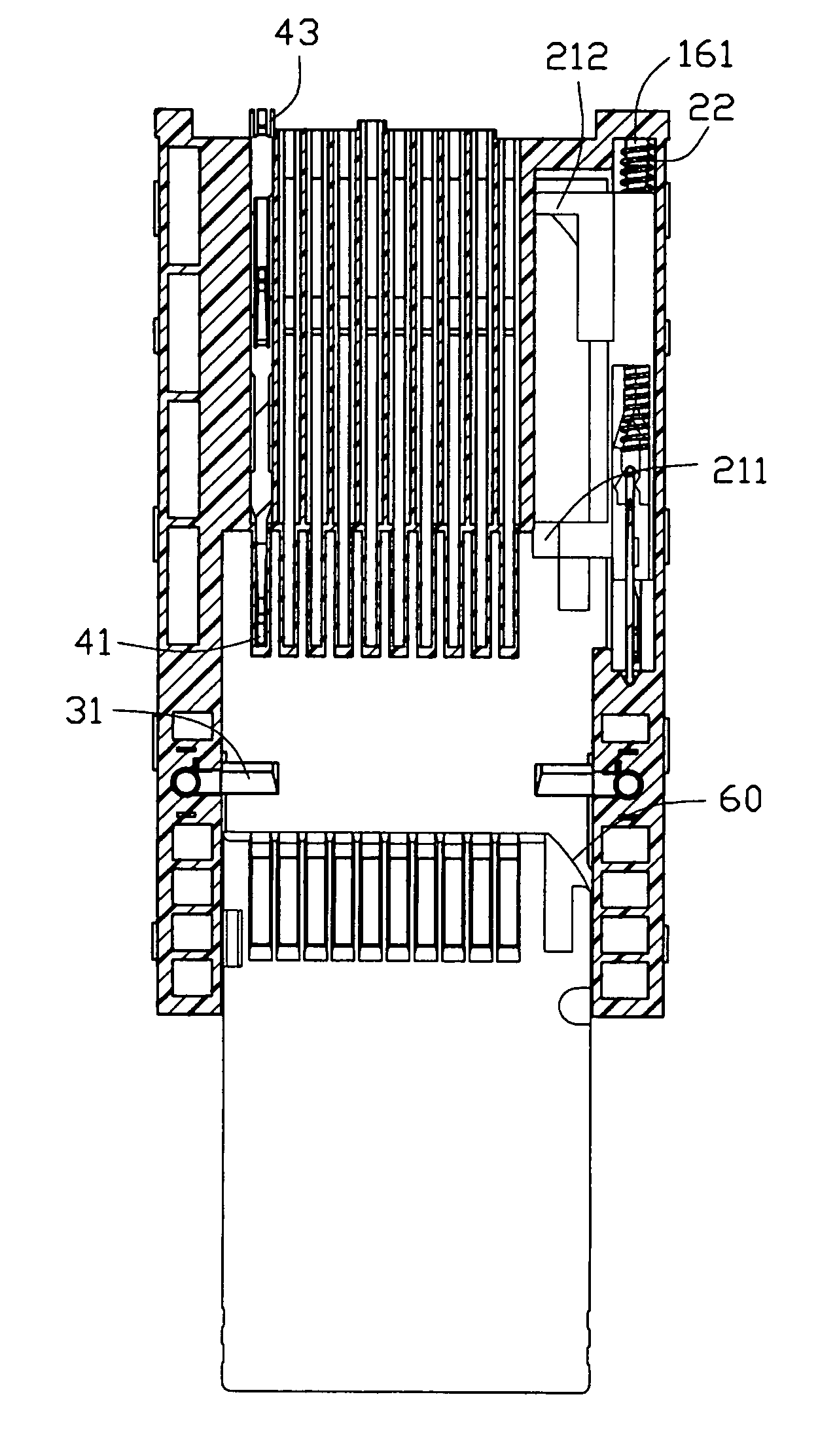
The present invention provides a card connector that can prevent misinsertion of cards. The connector has an insulating housing with two card receiving spaces, a plurality of contacts, and an anti-misinsertion appliance. The appliance includes a shutter member and an actuator member that controls the shutter member to open and close. The actuator member has a guiding slope and engaging hole for engaging with the shutter member. When the actuator member is moved out, the shutter member can open the card receiving space completely for receiving the corresponding card.

Problems solved by technology

However, if one card connector can only load one card, more cards are needed more card connectors to load, thus occupying a lot of areas of the electrical appliances and interfering with downsizing of the electrical appliances.
Especially, thus the MMC is easily inserted into the inserting cavity of the SD card because of misinsertion, then damaging the card connector.

Method used


Image

  • Card connector
  • Card connector
  • Card connector

Examples


Embodiment Construction

[0020]As shown in FIGS. 1 to 10, the card connector 1 of the present invention can be used commonly for a thin, short, small card such as a MS Duo card and a thick, long, large card such as a MS card. The present invention, however, is not limited to the use of these cards but also be applied satisfactorily to other memory cards such as SD cards and IC cards.

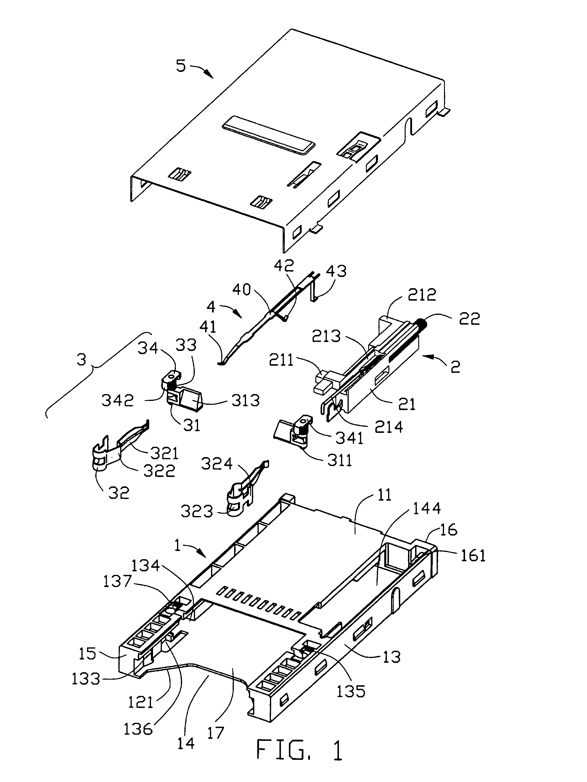
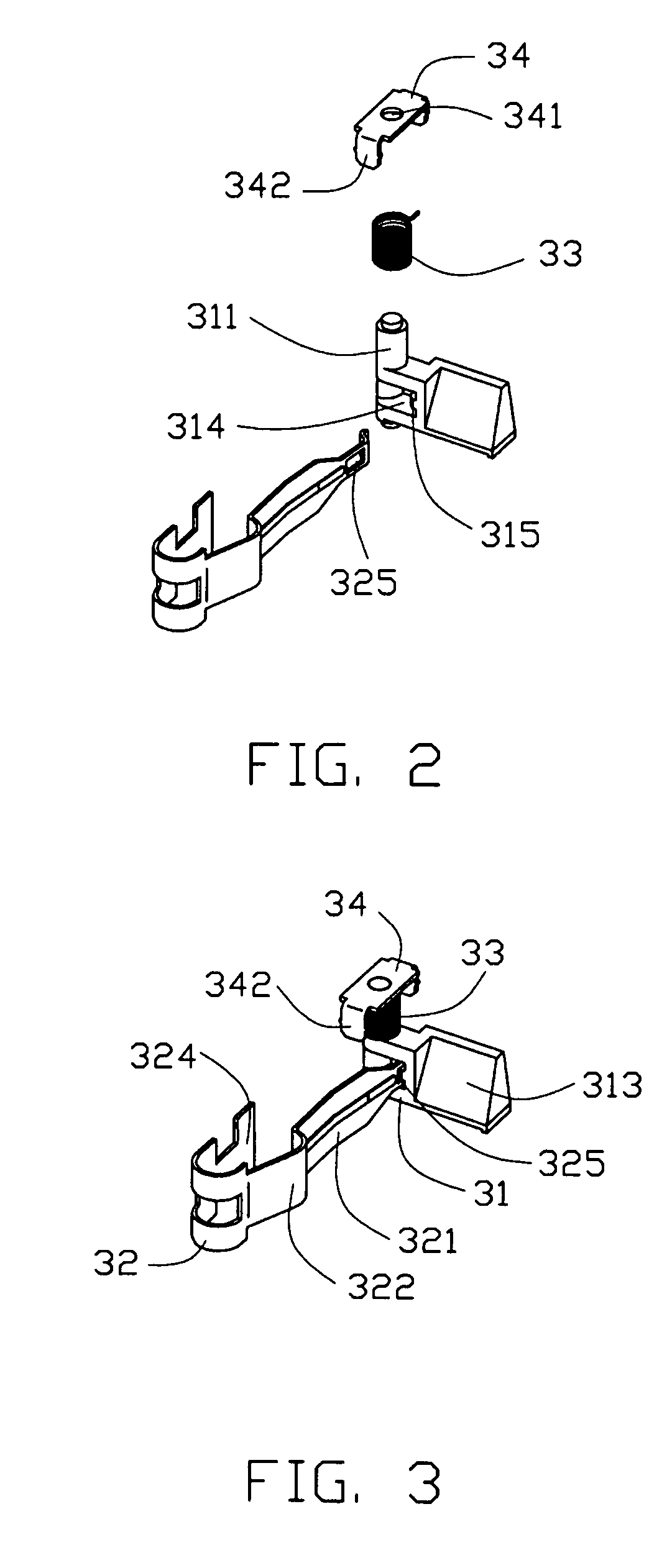
[0021]Referring to FIG. 1, the card connector of the present invention comprises an insulating housing 1, an ejector 2, an anti-misinsertion appliance 3, a plurality of electrical contacts 4 and a shielding member 5.

[0022]The housing 1 is approximately box-shaped and the shielding member 5 is used in combination with the housing 1. The housing 1 defines a card receiving space (not labeled) among an end wall 16, a pair of side walls 13, a top wall 11 and a bottom wall 12 thereof. The top wall 11 is approximately formed on rear part of the housing 1. The housing 1 is opened at a front face 15 thereof to form a card insertion openi...


PUM


Abstract

A card connector comprises an insulating housing defining a card receiving space for accommodating two kinds of different cards in size; a plurality of contacts retained in the housing, an anti-misinsertion appliance disposed in the housing, and comprising a shutter member and an actuator member for controlling the shutter member to open and close and the actuator formed with a locking hole for engaging with a mating portion of the shutter member and having a guiding slope extending from the second card cavity to the first card cavity; and when the actuator member is moved outwardly from the card receiving space because of an outer force, the shutter member can open the card receiving space completely for receiving the corresponding card.

Description

BACKGROUND OF THE INVENTION[0001]1. Field of the Invention[0002]The present invention relates to a card connector, especially to a card connector which has anti-misinserting appliances. The instant application relates to two contemporaneously filed applications each having the same applicant, the same title and the same assignee with the instant application.[0003]2. Description of Related Art[0004]With development of electrical appliances such as portable telephones, digital cameras, PDA (personal digital assistance), portable audio and the like, a lot of different kinds of cards such as a SD (super density, secure digital) card, a CF (compact flash) card, a MMC (multimedia card), a MS (memory stick) card, a MS Duo (memory stick duo) card and an XD (xd-picture) card are widely used in the field of the electronics. Because different cards have different external dimensions, thus different card connectors are needed loading corresponding different cards. However, if one card connector...

Claims


Application Information

Patent Timeline
Patent Type & Authority Patents(United States)
IPC IPC(8): H01R13/44
CPCH01R13/4536H01R27/00H01R13/64
Inventor SHEN, GUOJIANLI, REN-CHIH
Owner HON HAI PRECISION IND CO LTD
Learn More