Valve timing controller
a timing controller and timing controller technology, applied in the direction of valve drives, machines/engines, output power, etc., can solve the problems of detecting the lower limit value, the generation of control signals using the control circuit and the electrical conducting operation of the motor using the driving circuit cannot be realized
- Summary
- Abstract
- Description
- Claims
- Application Information
AI Technical Summary
Benefits of technology
Problems solved by technology
Method used
Image
Examples
first embodiment
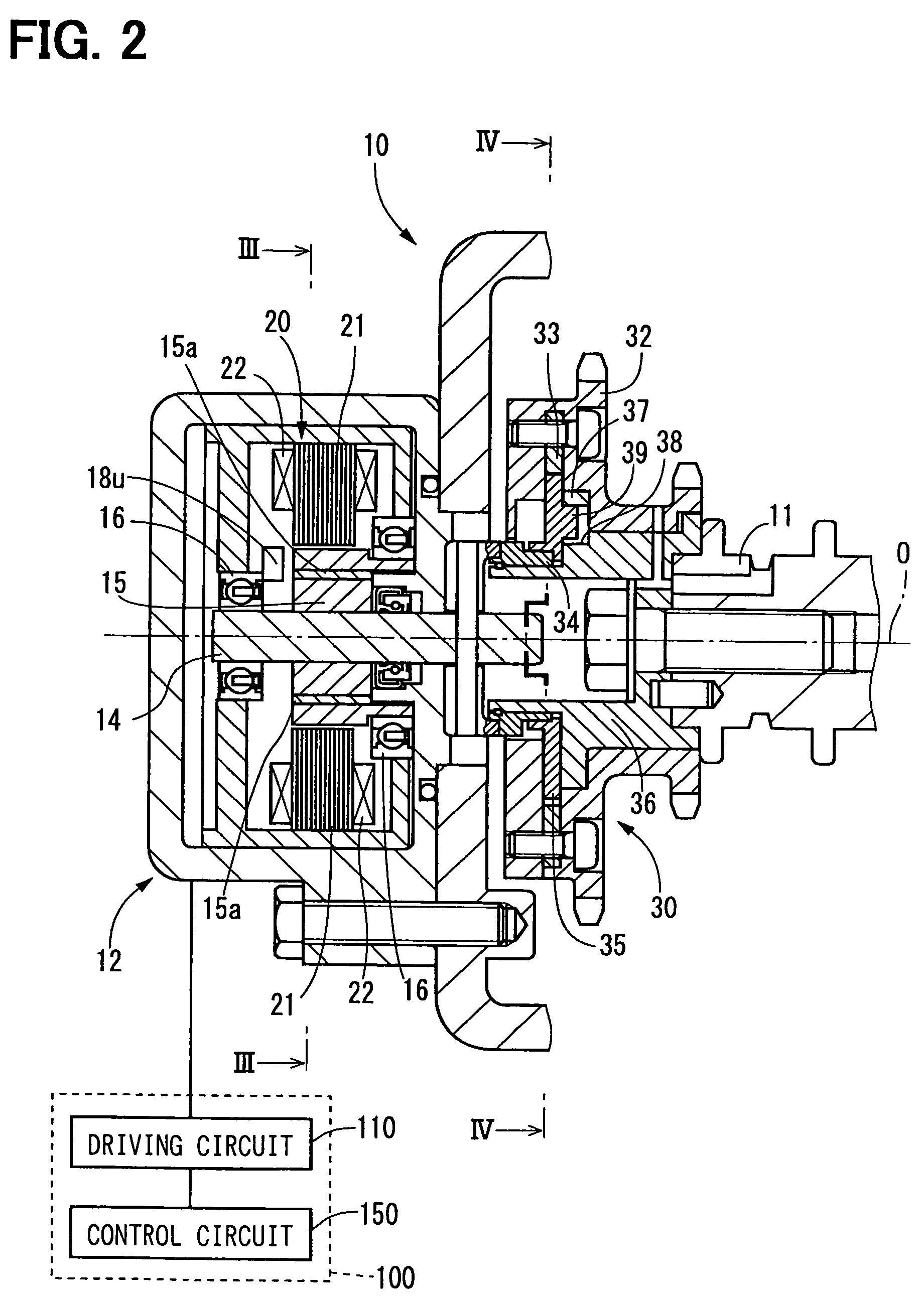
[0030]A valve timing controller in accordance with a first embodiment of the present invention is shown in FIGS. 2 to 4. The valve timing controller 10 additionally arranged in the engine of a vehicle adjusts valve timing with respect to an intake valve or an exhaust valve of the engine by utilizing the rotation torque of a motor 12.
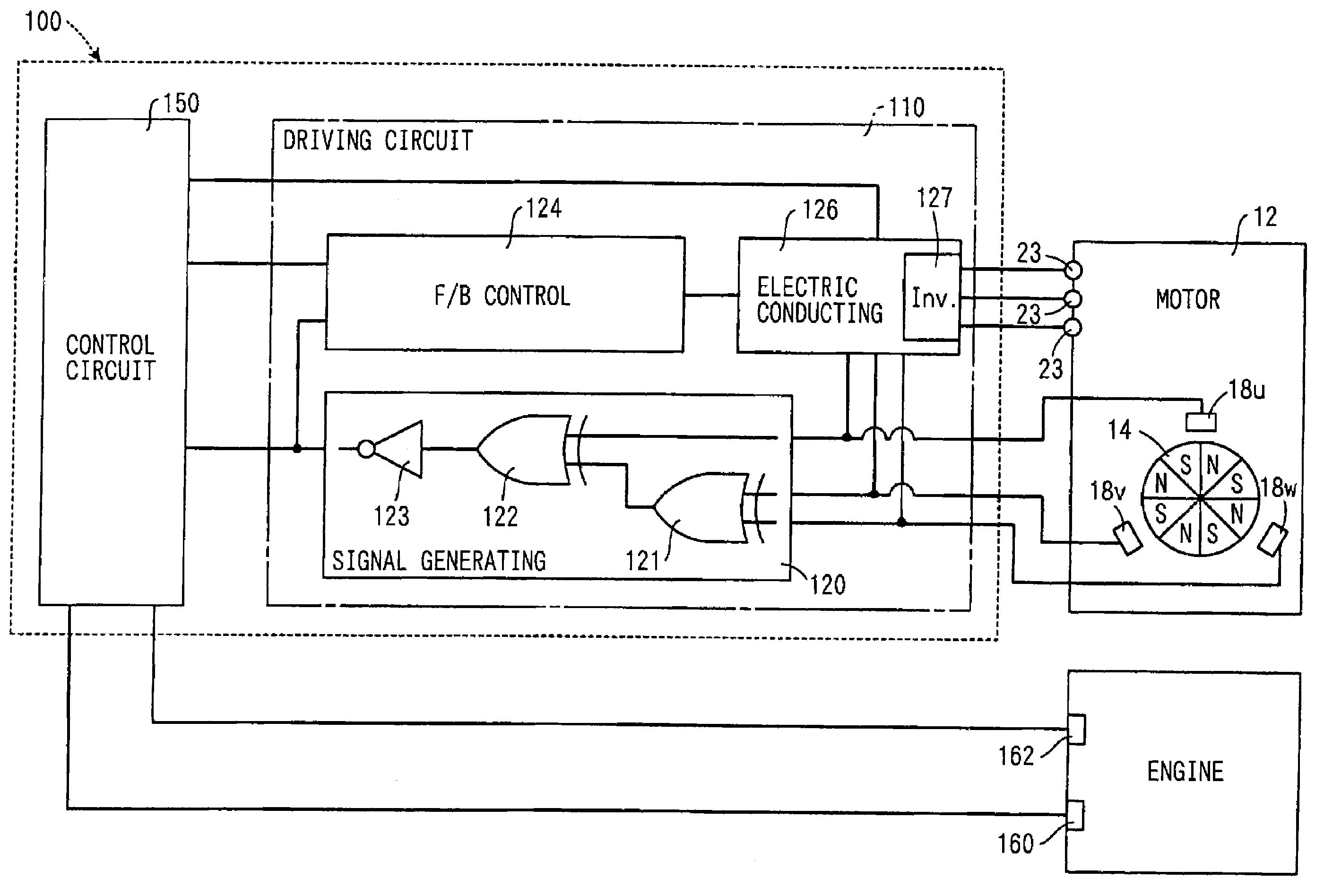
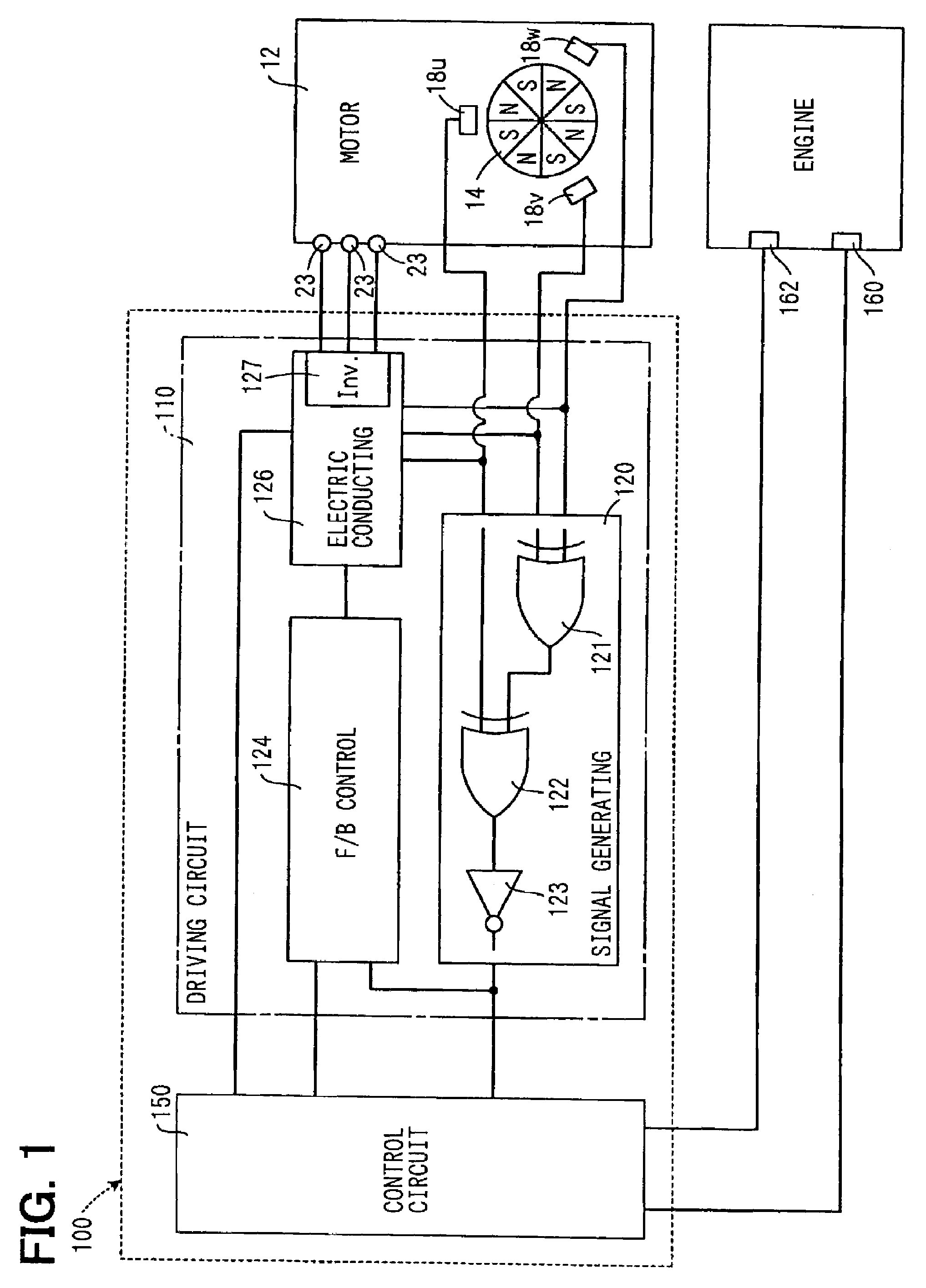
[0031]As shown in FIGS. 2 and 3, the motor 12 of the valve timing controller 10 is a three-phase brushless motor having a motor shaft 14, a bearing 16, Hall effect elements 18u, 18v, 18w as rotation position sensors, and a stator 20.
[0032]The motor shaft 14 is supported by two bearings 16 and can be rotated in the normal and reverse directions around the axis O. In this embodiment, the clockwise direction of FIG. 3 among the rotating directions of the motor shaft 14 is set to the normal rotating direction, and the counterclockwise direction of FIG. 3 is set to the reverse rotating direction. The motor shaft 14 forms a rotor portion 15 of a disk shape pro...
second embodiment
[0060]As shown in FIG. 8, a second embodiment of the present invention is a modified example of the first embodiment. The substantial same constructional portions as the first embodiment are designated by the same reference numerals, and their explanations are omitted.
[0061]A motor controller 200 of the second embodiment has a rotation signal generating circuit 210 corresponding to the rotation signal generating section 120 of the first embodiment as a circuit different from a driving circuit 220. In the motor controller 200 of such a second embodiment, effects similar to those in the case of the motor controller 100 of the first embodiment are also obtained.
third embodiment
[0062]As shown in FIG. 9, a third embodiment of the present invention is a modified example of the first embodiment, and the substantial same constructional portions as the first embodiment are designated by the same reference numerals and their explanations are omitted.
[0063]In a motor controller 250 of the third embodiment, a control circuit 260 is connected to Hall effect elements 18u, 18v, 18w through a driving circuit 270. The control circuit 260 receives a detecting signal generated by each of the Hall effect elements 18u, 18v, 18w as a motor rotation signal showing the real rotating position θ of the motor shaft 14. The control circuit 260 calculates the absolute value of the real rotation speed Rm of the motor shaft 14 by realizing a function similar to that of each of gates 121, 122, 123 of the rotation signal generating section 120 of the first embodiment, and also calculates the sign of the real rotation speed Rm similarly to the rotation signal generating section 120 of ...
PUM
 Abstract
Description
Claims
Application Information
 - R&D
- Intellectual Property
- Life Sciences
- Materials
- Tech Scout
- Unparalleled Data Quality
- Higher Quality Content
- 60% Fewer Hallucinations
Browse by: Latest US Patents, China's latest patents, Technical Efficacy Thesaurus, Application Domain, Technology Topic, Popular Technical Reports.
© 2025 PatSnap. All rights reserved.Legal|Privacy policy|Modern Slavery Act Transparency Statement|Sitemap|About US| Contact US: help@patsnap.com


