Medical drilling machine

a drilling machine and drilling technology, applied in the field of medical drilling machines, can solve the problems of difficult to form ideal bolt holes, difficulty in prompt correction of holes, and misalignment of axial centers, so as to relieve burden on users and achieve the effect of boring an accurate hol

Inactive Publication Date: 2006-07-11
HOYA TECHNOSURGICAL CORP
View PDF6 Cites 11 Cited by
  • Summary
  • Abstract
  • Description
  • Claims
  • Application Information

AI Technical Summary

Benefits of technology

[0014]The present invention has been made to solve the above-mentioned problems, and it is therefore an object of this invention to provide a medical drilling machine that relieves burden to a user such as a doctor, while facilitating the boring of an accurate hole.
[0017]According to this construction, by confirming the shape of the guides beforehand, the user can accurately read the slant direction of the drill bit from the relative misalignment between the first and the second guides. As a result, the slant of the drill bit can be corrected quickly, to enable formation of the drill hole substantially corresponding to direction of the ideal axial line. This also contributes to alleviation of burden (work) for the doctor or other user.
[0021]The above-mentioned construction enables effective exploitation of the first and the second bearings, which are already arranged coaxially with the central axis for functional reasons, thus enabling the simple construction and reduction of manufacturing costs.
[0023]In a further aspect of the above-mentioned invention, it is desirable that the casing is provided with a drive motor for making the drive shaft rotate via the force transfer mechanism, and a battery for the drive motor. According to this construction, the entire machine becomes a single unit and becomes easier to use, enabling accurate positioning of the drill bit. Therefore, since the above-mentioned first and second guides can be utilized effectively, the slant of the drill bit can be corrected smoothly using on the guides.
[0025]The doctor or other user typically holds the medical drilling machine at various angles. Therefore, by adopting the above-mentioned construction the battery, the grip portion, the drill bit (the drive shaft) and the drive motor are lined up one after the other such that the heavier battery and the drive motor are positioned at either end, and the grip portion and the drill bit which function as a fulcrum or point of support are arranged between the battery and the drive motor. Therefore, the balance properties of the device as a whole are excellent, and the drill bit can be positioned quickly by gripping the grip portion, in addition to alleviating the burden on the arm of the doctor or other user.

Problems solved by technology

However, it is difficult actually to form an ideal bolt hole.
The reason for this is that when the drill bit 19 is advanced forward in the direction of the ideal axial line R, there inevitably occurs misalignment of the axial center, or slanting of the drill bit 19, or other similar problems, and prompt correction thereof was difficult.
When the doctor sees this image, the doctor understands that the drill bit 19 has slanted along a long axis D1 across the length of the oval ring D. However, there still is a problem in that the doctor can not judge which direction the drill bit 19 is slanting along the long axis D1.
As a result, the doctor would adjust the direction of the drill bit 19 in the wrong direction, causing the drill hole C to slant even further, or requiring time to adjust the direction of the drill bit 19, thus creating a problem of lengthening the operation time.
Furthermore, since the drive motor 21 is provided as a separate unit from the medical drilling machine 1, there was a problem that it was very difficult for the doctor to hold.
With this structure it was fundamentally difficult to position the drill bit 19 accurately and / or maintain the position.

Method used


Image

  • Medical drilling machine
  • Medical drilling machine
  • Medical drilling machine

Examples


Embodiment Construction

[0044]Hereinafter, an example of an embodiment of the present invention will be described in detail, with reference to the drawings.

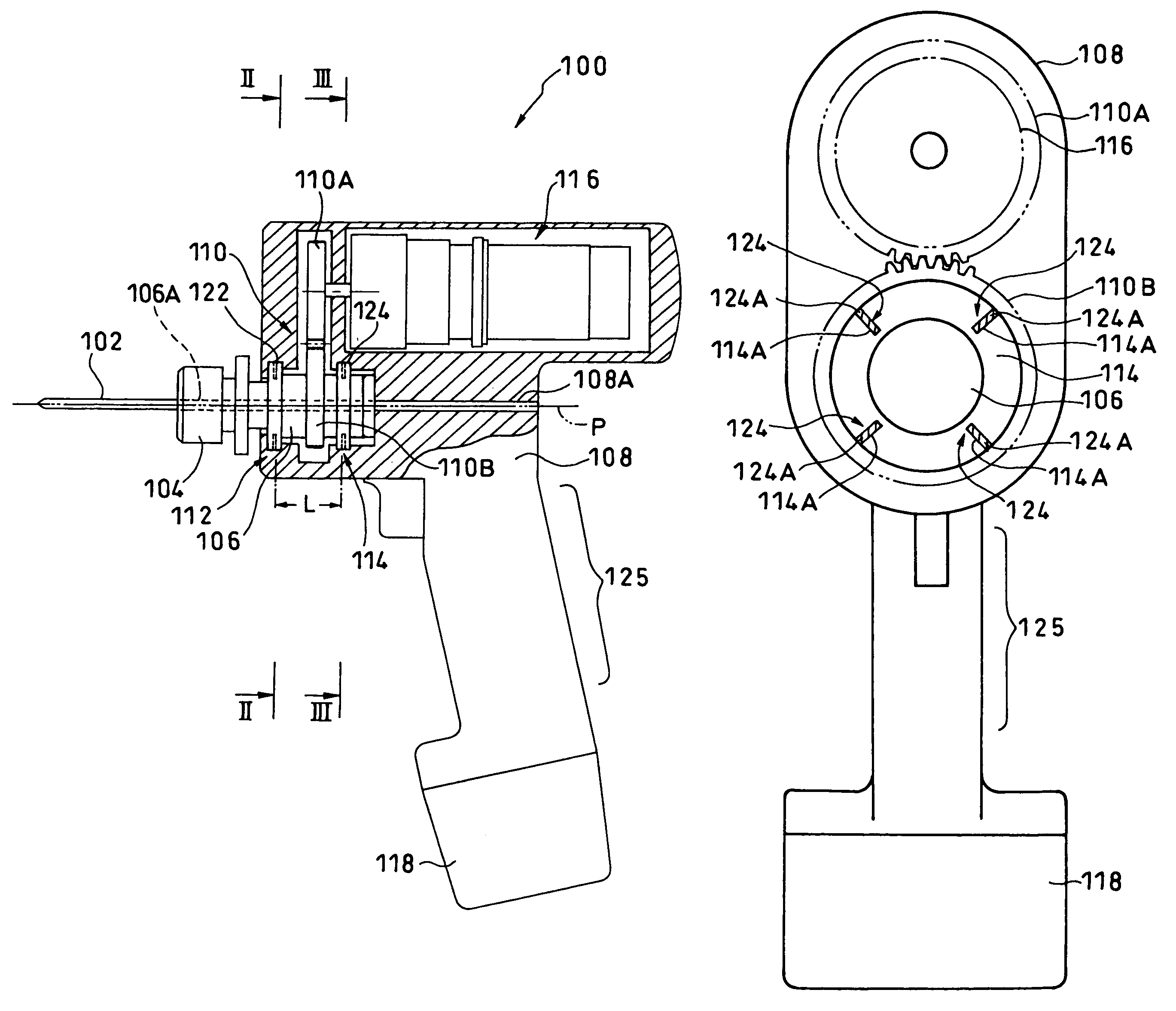
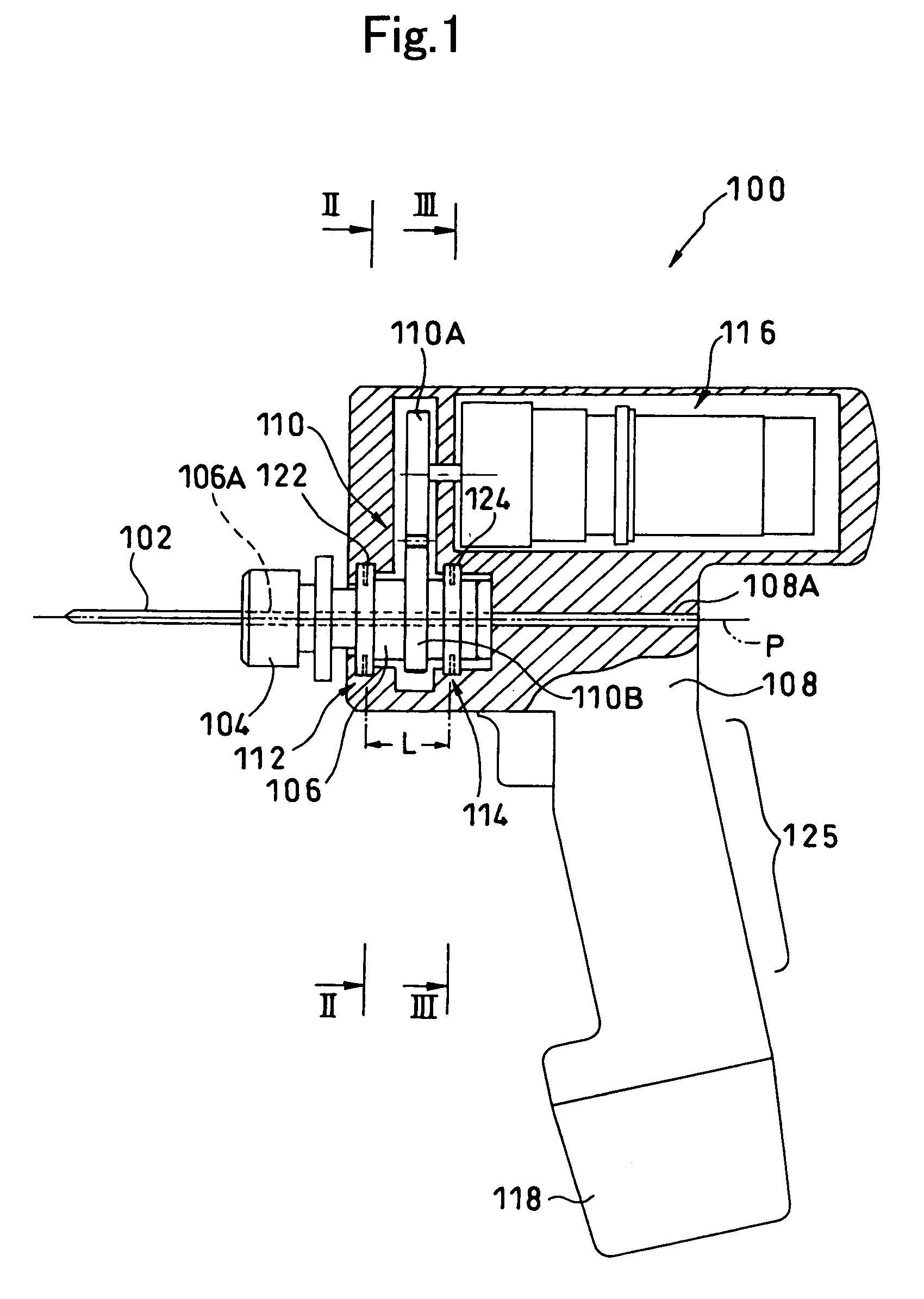
[0045]FIG. 1 shows a medical drilling machine (hereinafter, “drill machine”) 100, in accordance with a first embodiment of the present invention.

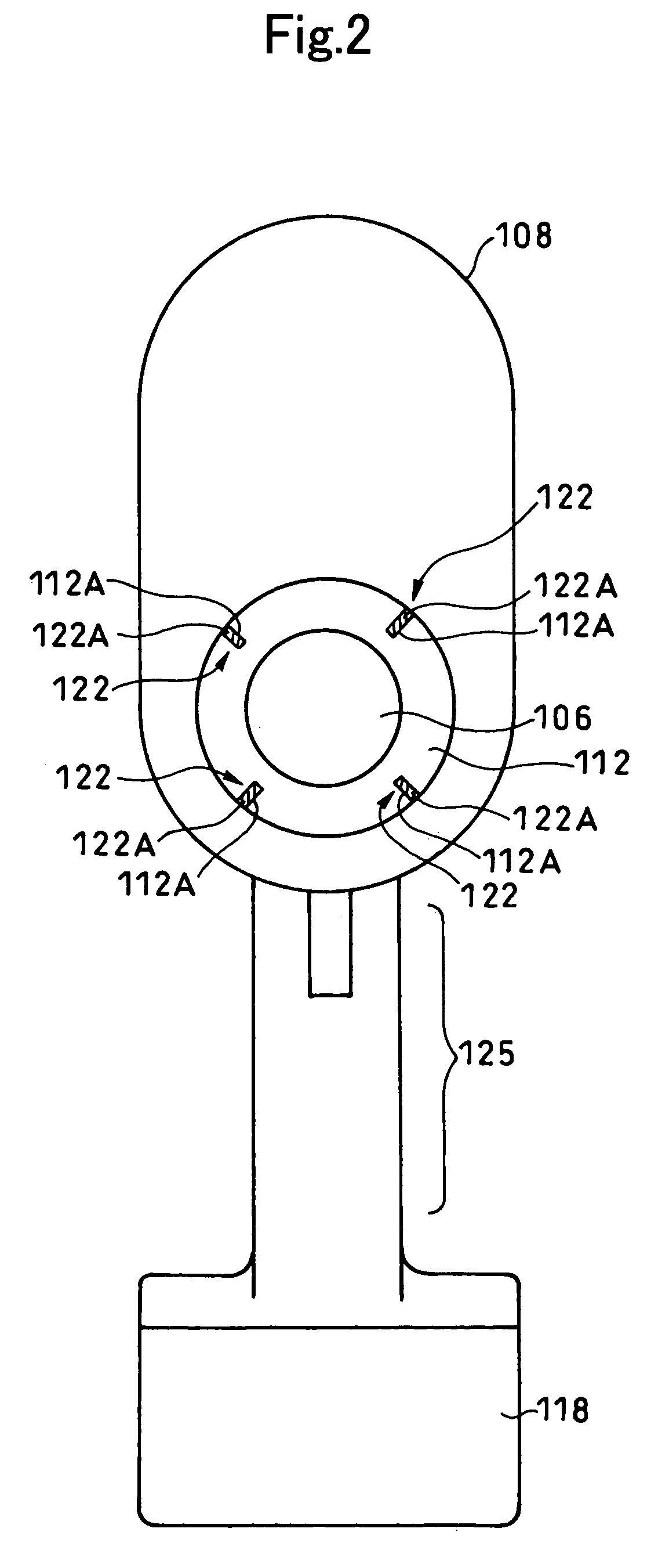
[0046]The drill machine 100 includes: a drill bit 102; a drive shaft 106 gripping the drill bit 102 by means of a chuck 104 provided at the end of the drive shaft; a casing 108 capable of housing the drive shaft 106; and a force transferring mechanism 110 for transferring rotational force to the drive shaft 106.

[0047]The drive shaft 106 is held rotatably by a first bearing 112 and a second bearing 114 provided inside the casing 108. The drive shaft 106, both the bearings 112, 114, and the casing 108 are made of X-ray transparent material.

[0048]Note, however, that it is sufficient if only the part of the casing 108 around the drive shaft 106 is made of the X-ray transparent material. It is not necessary to make ...


PUM


Abstract

To facilitate positioning of a drill bit and alleviate burden to a user, a medical drill machine including a drive shaft gripping a drill bit, a casing constituted of X-ray transparent material and capable of housing the drive shaft, and a force transferring mechanism for transferring rotational force to the drive shaft is provided. In this medical drill machine, a first guide and a second guide constituted of X-ray opaque material are fixed at given positions along an axial direction of the drive shaft in the casing. Both guides are arranged coaxially with the axis of the drive shaft, and are formed in mutually different shapes. A slant direction of the drill bit can be recognized from any relative misalignment of the mutually different shapes of the guides included in an X-ray image along the ideal axial line.

Description

BACKGROUND OF THE INVENTION[0001]1. Field of the Invention[0002]The present invention relates to a medical drilling machine with a drive shaft which is rotatably held and is housed in an X-ray transparent casing, and more particularly to a technique for achieving accurate boring operation.[0003]2. Description of the Related Art[0004]In surgical operation or the like, there are instances where a hole must be bored with a medical drilling machine at a position that is not directly observable inside the body of a patient. Typically, such holes are bored in bone or transplant materials transplanted into the body. When boring the holes at a position which is not directly observable, X-ray images must be used to position the drill bit accurately.[0005]FIG. 12 shows a conventional medical drilling machine disclosed in Japanese Patent Laid-Open Publication No. Hei 9-19437.[0006]This medical drilling machine 1 includes: a casing 11 made of X-ray transparent material; a drive shaft 16 housed ...

Claims


Application Information

Patent Timeline
IPC IPC(8): A61B17/16A61B17/17A61B17/56
CPCA61B17/1622A61B17/1725A61B17/1717A61B17/1703
Inventor KIMURA, JUNICHI
Owner HOYA TECHNOSURGICAL CORP
Why Eureka
Try Eureka