
System for indicating the position of a surgical probe within a head on an image of the head

a technology of surgical probe and head, which is applied in the field of system for indicating the position of surgical probe within the head on an image of the head, can solve the problems of cumbersome, if not impossible, and the inability of neurosurgeons to fully utilize scanning technologies in the operating room, and achieve the effects of reducing the risk of infection

Inactive Publication Date: 2006-07-04
SAINT LOUIS UNIVERSITY
View PDF196 Cites 213 Cited by
  • Summary
  • Abstract
  • Description
  • Claims
  • Application Information

AI Technical Summary

Benefits of technology

[0004]It is an object of this invention to provide a system which can determine the position of a probe within an object and display an image corresponding to the determined position. It is a further object of this invention to provide a system which can determine the position of an ultrasound probe relative to an object and, still further, which can display scan images from other scanning technologies corresponding to the scan images produced by the ultrasound probe. It is a further object of this invention to provide a system which can relate scan images of an object produced with one technology to scan images of the same object produced with another technology.

Problems solved by technology

However, the precision and accuracy of the scanning technologies have not become fully available to the neurosurgeon in the operating room.
Relating specific structures and locations within the brain during surgery to preoperative scanning technologies has previously been cumbersome, if not impossible.
Ventriculography carried a significant complication rate and accuracy in localization was marginal.

Method used


Image

  • System for indicating the position of a surgical probe within a head on an image of the head
  • System for indicating the position of a surgical probe within a head on an image of the head
  • System for indicating the position of a surgical probe within a head on an image of the head

Examples


Embodiment Construction

[0035]With the advent of modern scanning equipment and techniques, several stereotactic systems have been developed and are presently available. These stereotactic systems allow a surgeon to localize specific points detected on CT, MRI, PET, or MEG scans which have been previously generated prior to the surgical procedure being performed. In particular, the stereotactic systems allow the selection of specific points detected on the scans to be localized within the brain by the surgeon during the surgical procedure using a mechanical device.

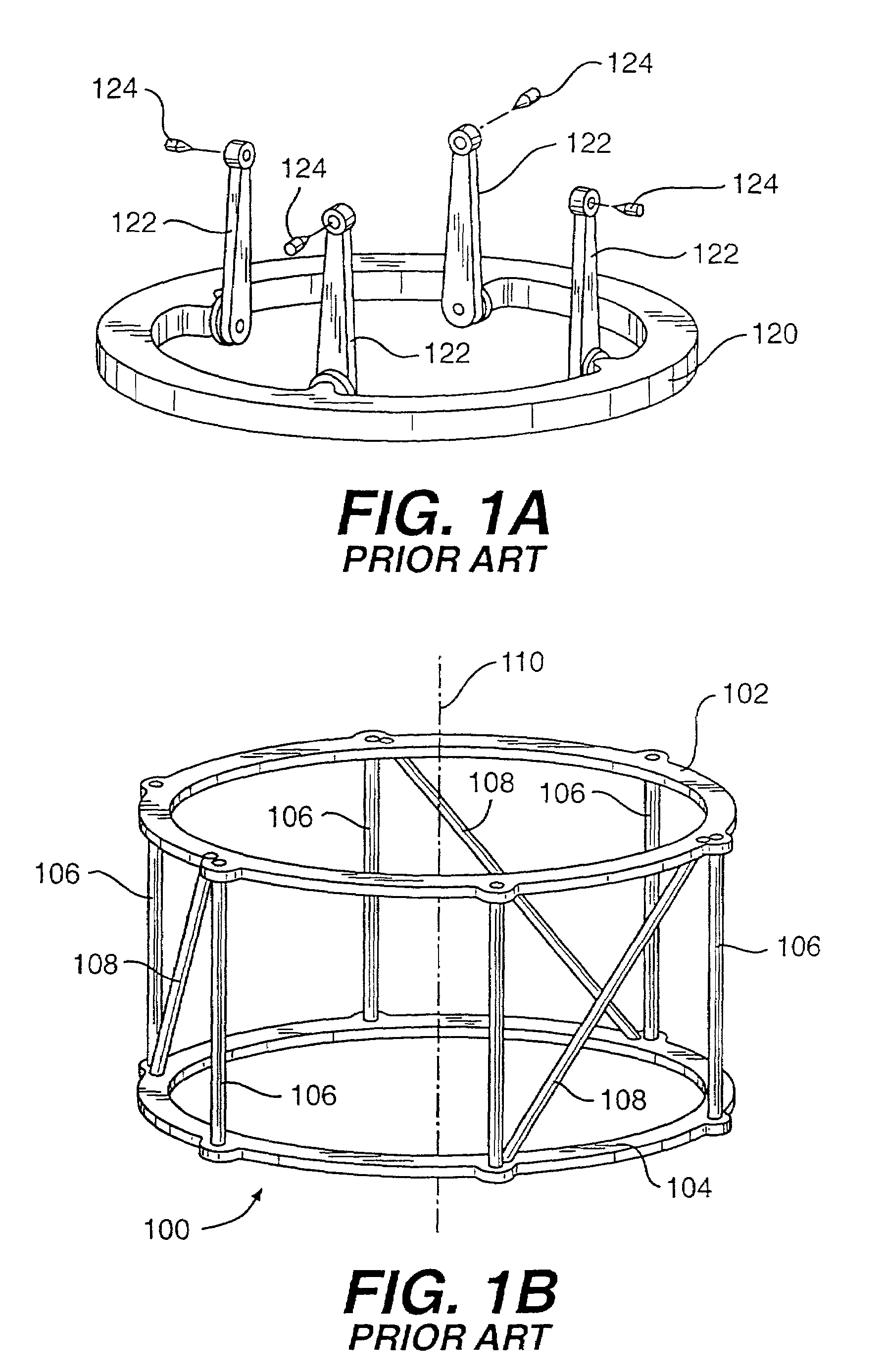
[0036]In use, the prior art stereotactic systems often require a base such as a ring 120 (also known as a BRW head ring) in FIG. 1A. Ring 120 is firmly attached to the patient's skull via uprights 122 and sharp pins 124 throughout scanning and surgery.

[0037]During scanning, some form of localizing device, such as a cylindrical structure 100 in FIG. 1B, is attached to ring 120. Structure 100 comprises an upper circular ring 102 in parallel with a l...


PUM


Abstract

A system for indicating a position within an object such as a head of a body of a patient. The position of a tip of a probe relative to a reference is determined. The position of reference points of the object relative to the reference is measured. The determined position is translated into an image coordinate system and an image of the object is displayed.

Description

[0001]This application is a divisional application of 09 / 457,699, filed Dec. 9, 1999 U.S. Pat. No. 6,374,135, which is a continuation of 09 / 243,804, filed Feb. 3, 1999, U.S. Pat. No. 6,076,008, which is a continuation of 08 / 477,561, filed Jun. 7, 1995, U.S. Pat. No. 5,891,034, which is a continuation of 08 / 053,076, filed Apr. 26, 1993, abondoned, which is a continuation-in-part of 07 / 909,097, filed Jul. 2, 1992, U.S. Pat. No. 5,383,454 and is a continuation-in-part of 07 / 858,980, filed May 15, 1992, abandoned, and said 07 / 909,097, filed May 15, 1992 is a continuation of 07 / 600,753, filed Oct. 19, 1990, abandoned and said 07 / 858,980 is a continuation-in-part of PCT / US91 / 07745, filed Oct. 16, 1991, which is a continuation-in-part of 07 / 600,753, filed Oct. 19, 1990, abandoned.BACKGROUND OF THE INVENTION[0002]Precise localization of position has always been critical to neurosurgery. Knowledge of the anatomy of the brain and specific functions relegated to local areas of the brain are cr...

Claims


Application Information

Patent Timeline
IPC IPC(8): A61B6/00A61B5/00A61B5/055A61B5/06A61B5/107A61B6/12A61B8/00A61B17/88A61B19/00
CPCA61B5/0064A61B5/06A61B5/1077A61B6/12A61B6/501A61B6/5247A61B8/00A61B8/5238A61B19/20A61B19/52A61B19/5244A61B5/0073A61B8/0808A61B5/055A61B19/203A61B19/54A61B2019/461A61B2019/505A61B2019/5231A61B2019/5255A61B2019/5263A61B2019/5265A61B2019/5268A61B2019/5272A61B2019/5276A61B2019/5287A61B2019/5289A61B2019/5425A61B2019/5429A61B2019/5445A61B2019/5454A61B2019/5479A61B2019/5483A61B2019/5495A61B2090/3983A61B90/10A61B90/36A61B2090/373A61B2034/2055A61B2034/2063A61B2034/2068A61B2034/2072A61B2090/363A61B2090/3945A61B2090/3979A61B2090/3995A61B34/20A61B2090/364A61B90/14A61B2090/061A61B2034/105A61B2034/2065A61B2090/378A61B90/39A61B2090/3925A61B2090/3929A61B2090/3954A61B5/061A61B5/702
Inventor BUCHOLZ, RICHARD D.
Owner SAINT LOUIS UNIVERSITY
Learn More