
Apparatus for securing a workpiece

a technology for workpieces and accessories, applied in the direction of clamps, manufacturing tools, and vices, can solve the problems of inability to easily transport traditional vises, limited applications of bar clamps and c-clamps, and inability to meet the requirements of use,

Inactive Publication Date: 2006-06-27
JPW IND
View PDF107 Cites 49 Cited by
  • Summary
  • Abstract
  • Description
  • Claims
  • Application Information

AI Technical Summary

Problems solved by technology

Unfortunately, however, traditional vises are not designed to be readily transported from one place to another so that the vise may be used in locations remote from the bench top.
This may be due in part to the weight of the vise (which is often heavy), or in the alternative due to the way in which it is mounted to the bench top (which typically requires a base of the vise to be bolted to a work surface).
Applications in which bar clamps and C-clamps are used, however, are limited due to their inability to be used in applications which require a stationary bench top mounted apparatus for securing a workpiece.
For example, in applications where the workpiece is not self standing or self supporting, a bar clamp may be an unacceptable alternative due to its inability to support the workpiece as desired and / or in the position desired.
Another problem associated with traditional bar clamps is that the clamp members and bars of the bar clamp are sold as a set rather than being sold separately.
This prevents users from purchasing one set of clamp members for use with varying bar lengths, or from purchasing replacement clamp members and bars.
In addition, the inability to adjust the position or direction with which the clamps and / or jaw assemblies of a bar clamp are capable of engaging a workpiece may also prevent such tools from being used in certain applications.
Although some bench vises have a rotatable jaw feature which may be useful in such applications, the relative immobility of the bench vise may preclude it from being used for the reasons discussed above.
Furthermore, the inability to add and replace clamps and / or the jaw assemblies of bar clamps further limits the use of such tools in a variety of applications.
For example, when working with a workpiece that requires the clamp to engage or secure the workpiece in a plurality of positions, but does not have enough room for multiple bar clamps to be positioned thereon, a bar clamp may not be sufficient for the task at hand due to the operator's inability to add clamps and / or jaw assemblies.
Moreover, the inability to replace broken clamps and / or jaw assemblies or to use different types of jaws and jaw assemblies may also prevent a user from using a bar clamp in applications where such options are needed.

Method used


Image

  • Apparatus for securing a workpiece
  • Apparatus for securing a workpiece
  • Apparatus for securing a workpiece

Examples


Embodiment Construction

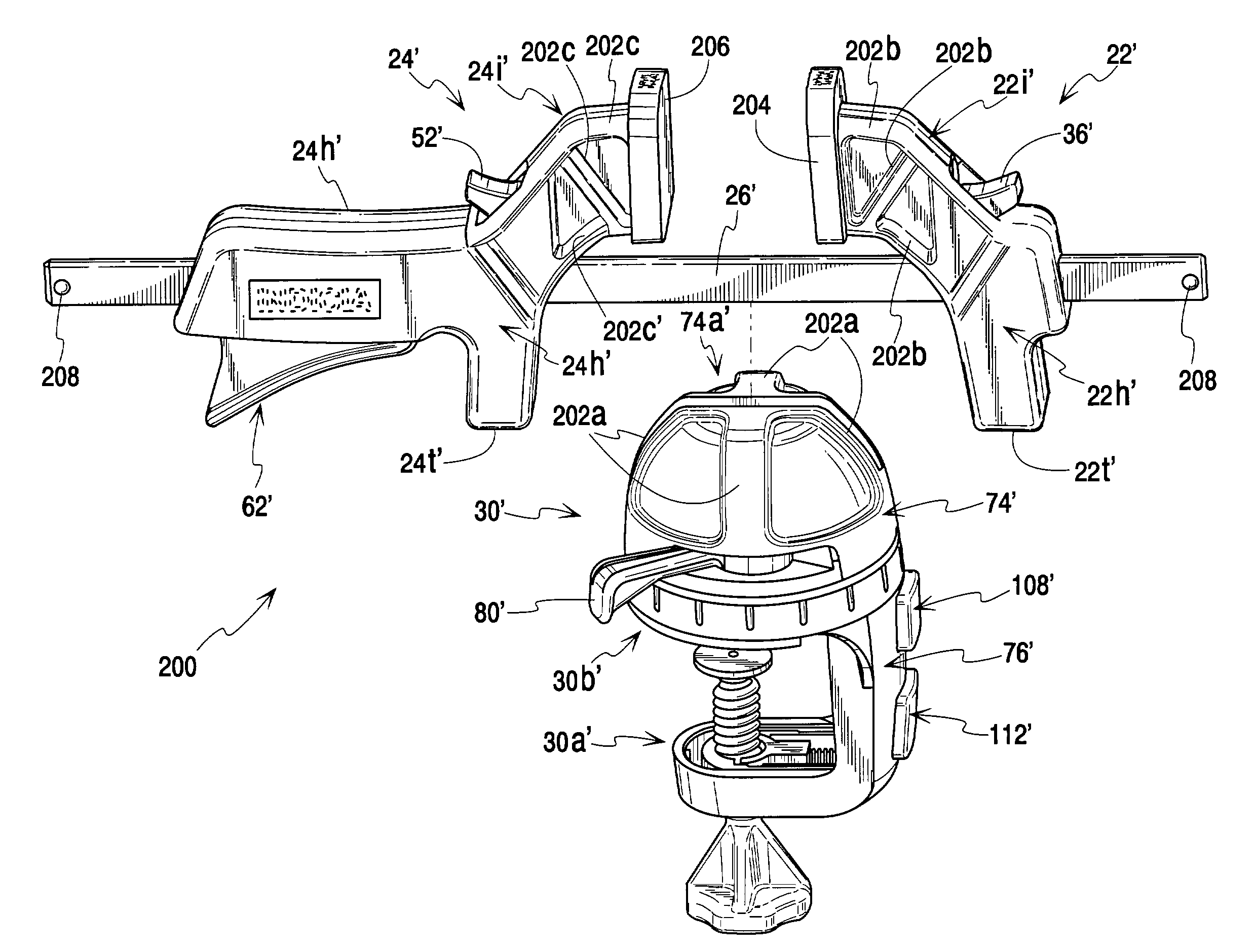
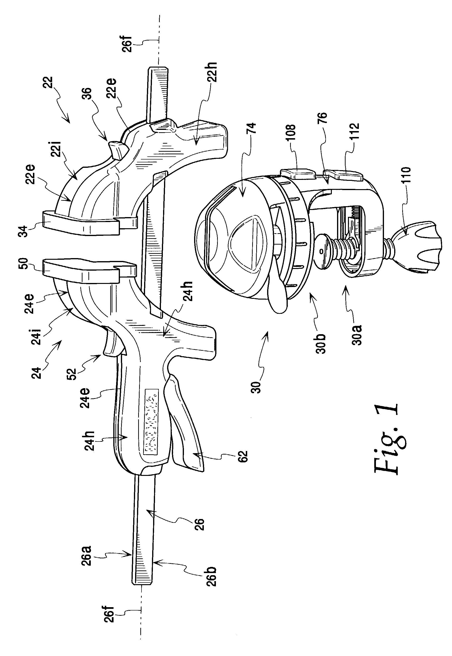
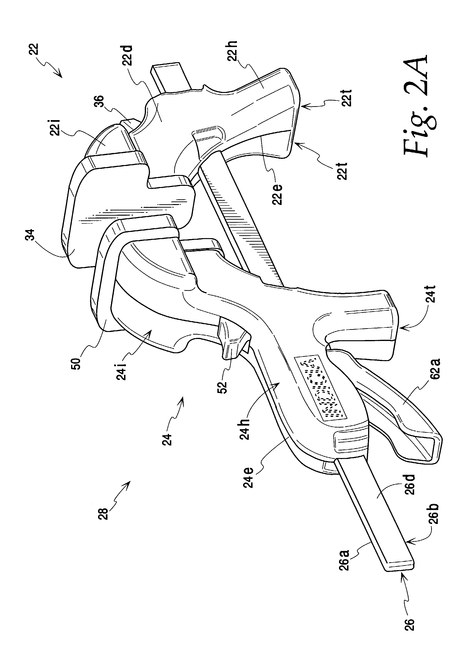
[0046]Referring now to the drawings, and especially FIGS. 1–7H, an apparatus for securing a workpiece is shown and is generally identified by reference numeral 20. The apparatus 20 includes a pair of clamp members 22 and 24, and a transportable elongate member, such as a bar 26, to which the clamp members 22 and 24 are adjustably mounted for being shifted between clamped and unclamped positions to secure a workpiece. As shown, clamp member 22 remains stationary on member 26 during a workpiece clamping operation while the other clamp member 24 is advanced therealong by a trigger mechanism 62 thereof to form a bar clamp portion 28 of the preferred apparatus 20 herein. The apparatus further includes a base 30 having an upper portion 74 for connecting the elongate member 26 to the base 30, and a lower portion 76 with a base securing mechanism 30a, such as a clamp mechanism, for mounting the base to a support surface such as a table top. In this manner the bar clamp assembly 28 is remova...


PUM


Abstract

An apparatus for securing a workpiece comprising first and second clamp members, and a transportable elongate member to which the clamp members are mounted and are operable for being shifted between work engaging and work releasing positions. In one form, the apparatus may be configured with clamp members capable of being fully removed from the elongate member and placed back thereon while maintaining the operability of the clamp members. At least one of the clamp members may be capable of being mounted on the elongate member in a plurality of directions, or may include jaw assemblies which are removable from and / or rotatable with respect to the elongate member. In addition, the apparatus may include a base for securing the base to a work surface and a catch for securing the elongate member to the base. In another form, the base may be configured to receive and secure the elongate member in a plurality of directions.

Description

BACKGROUND OF THE INVENTION[0001]This invention relates generally to an apparatus for securing a workpiece and more particularly to a bar clamp having a variety of clamp features and a mating base to which the bar clamp may be mounted for performing additional workpiece securing applications.[0002]Presently, the tool industry offers a variety of tools for securing workpieces such as vises, bar clamps, C-clamps and the like. Each of these tools offer advantages over their alternatives. For example, a vise may be mounted to a work surface, such as a bench top, in order to provide a strong and sturdy apparatus for securing a workpiece. Unfortunately, however, traditional vises are not designed to be readily transported from one place to another so that the vise may be used in locations remote from the bench top. This may be due in part to the weight of the vise (which is often heavy), or in the alternative due to the way in which it is mounted to the bench top (which typically requires...

Claims


Application Information

Patent Timeline
Patent Type & Authority Patents(United States)
IPC IPC(8): B25B1/00B25B5/06
CPCB25B5/068
Inventor GERRITSEN, JOHN T.PHILLIPS, WILLIAM J.
Owner JPW IND
Learn More