
Device communications of an implantable medical device and an external system

Inactive Publication Date: 2006-06-20
CARDIAC PACEMAKERS INC
View PDF140 Cites 160 Cited by
  • Summary
  • Abstract
  • Description
  • Claims
  • Application Information

AI Technical Summary

Benefits of technology

[0010]Communication may be established between an implantable medical device and an external unit wherein the implantable medical device has a transmit and a receive frequency that are separated by a fixed difference. One or more signals are sent out from a transmitter of the external unit, and one signal of the one or more signals has a frequency that is close enough to the receive frequency for the implantable device to receive the one signal. A receiver of the implantable device receives the one signal, and a transmitter of the implantable device sends out a return signal at a transmit frequency in response to receiving the one signal. The receiver of the external unit receives the return signal and a frequency discriminator of the receiver measures a difference between the transmit frequency of the return signal and a receive frequency of the external unit. A processor of the external unit then alters the transmit frequency and receive frequency of the external unit by the measured difference.
[0011]Alternatively, communication may be established between an implantable medical device and an external unit wherein the implantable medical device has a transmit frequency and a receive frequency. A transmitter of the external unit sends out one or more signals wherein one signal of the one or more signals has a frequency that is close enough to the receive frequency for the implantable device to receive the one signal. A receiver of the implantable device receives the one signal and measures a first difference between the frequency of the one signal and the receive frequency. The transmitter of the implantable device sends out a return signal at the transmit frequency from the

Problems solved by technology

Management of patients with chronic disease consumes a significant proportion of the total health care expenditure in the United States.
Heart failure prevalence alone is estimated at over 5.5 million patients in 2000 with incidence rates of over half a million additional patients annually, resulting in a total health care burden in excess of $20 billion.
In addition to causing considerable physical and emotional trauma to the patient and family, event driven hospitalizations consume a majority of the total health care expenditure allocated to the treatment of heart failure.
Device follow-ups are labor intensive and typically require patients to make multiple clinic visits.
The conventional approach to communicating with the implantable device has drawbacks in that the patient must actively participate in the communication process.
However, providing automatic radio frequency communications abilities in the implant can lead to significant increases in cost, size, and power consumption.
The radio frequencies of transmission and reception by the implantable device are fairly unpredictable when using low-cost transceivers, such as surface acoustic wave (SAW) based devices, due to environmental effects and manufacturing tolerances.
Therefore, the external unit cannot communicate with the implant at exactly the same frequencies each time.
Furthermore, providing frequency synthesis in the implant to control the frequencies of transmission and reception is not a practical solution because frequency synthesis consumes more power than can be provided over a long-term basis, which is required by implants with lengthy life times. Therefore, radio frequency communications with the implant are troublesome.
However, environmental effects and manufacturing tolerances cause time drift between the clock of the implant and the clock of the external unit.
The uncertainty as to the proper time to communicate can cause the implant to power up in anticipation for communication at a different time than when the external unit attempts to communicate.
Therefore, opportunities to communicate may be completely lost because the devices are not properly synchronized.

Method used


Image

  • Device communications of an implantable medical device and an external system
  • Device communications of an implantable medical device and an external system
  • Device communications of an implantable medical device and an external system

Examples


Embodiment Construction

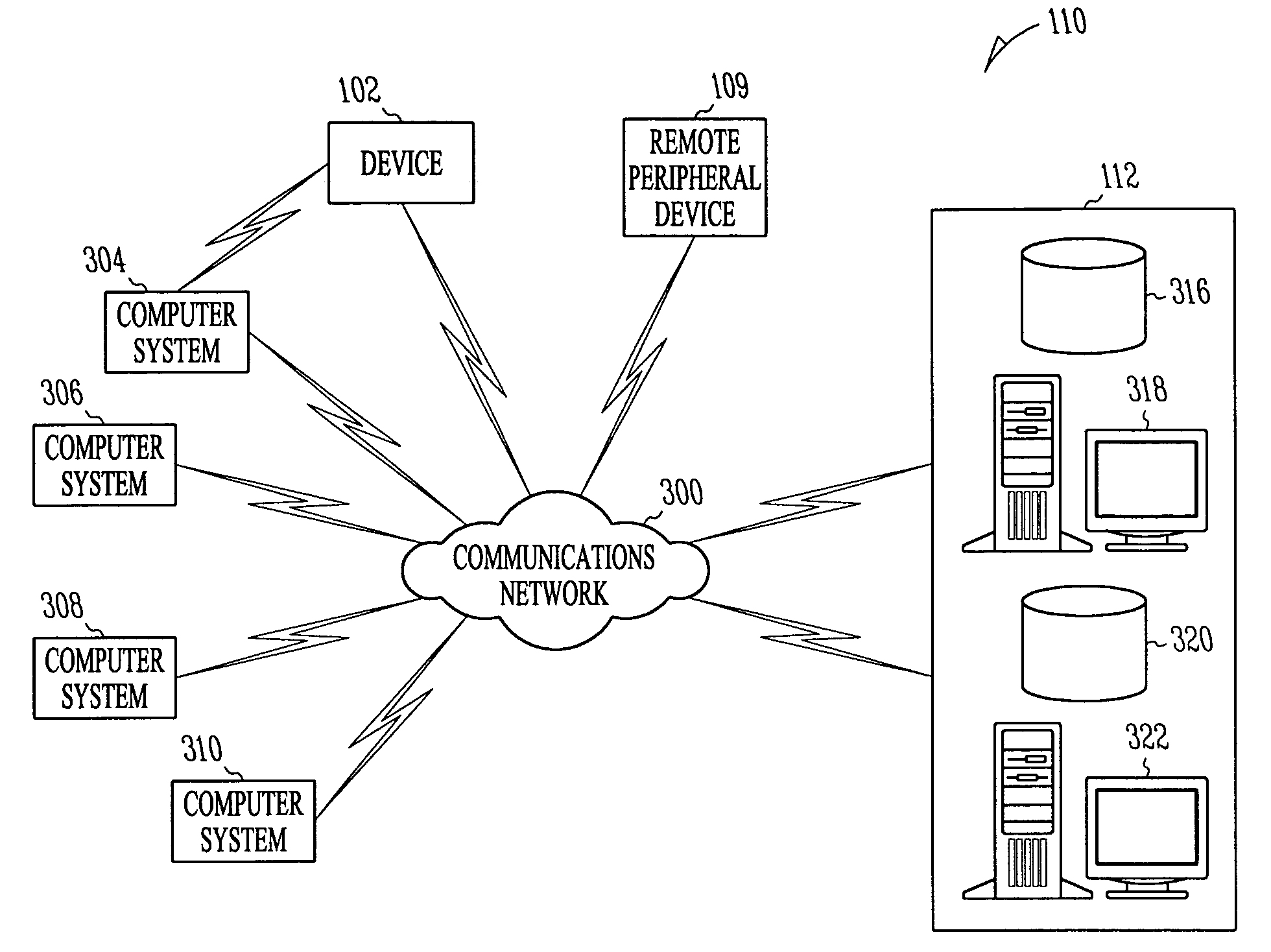
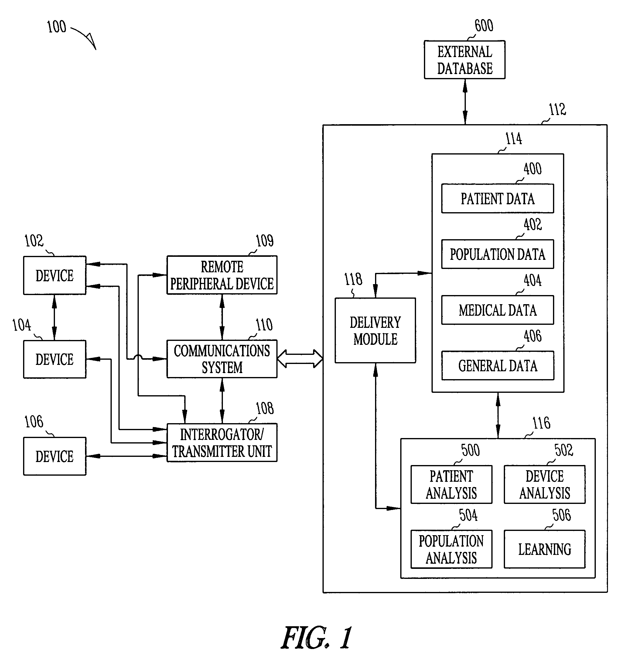
[0031]Prior to discussing the devices and communication protocols of the embodiments of the present invention, an example of an advanced patient management system is discussed to provide an example of an environmental context for the embodiments of the present invention. However, it is to be understood that the advanced patient management system described herein in conjunction with the embodiments of the present invention is only one example of an operating environment and it not to be taken in a limiting sense. For example, the embodiments of the present invention involving communication between an external device and an implantable medical device may operate without further interaction with an advanced patient management system and its associated communication system. The devices and communication protocols of the embodiments of the present invention are discussed below with reference to FIGS. 5–16 in section V. DEVICE COMMUNICATIONS.

[0032]An advanced patient management system is ...


PUM


Abstract

An implantable medical device, external unit, and method for establishing communication between them are disclosed. The external unit learns the frequencies of transmission and reception for the implant. The transmit frequency of the implant is learned by the external unit measuring a difference between the transmit frequency of the implant and the external unit's receive frequency. The receive frequency of the implant is learned by the measured difference between its transmit frequency and the receive frequency of the external unit when the implant has a fixed transmit and receive frequency difference. Otherwise, the receive frequency is learned by the implant measuring the difference between its receive frequency and the transmit frequency of the external unit and by sending an indication of the difference to the external unit through the return signal. The external unit may anticipate a beginning of the implant's preset communication period based on its internal clock.

Description

TECHNICAL FIELD[0001]The present system relates generally to advanced patient management systems, and particularly, but not by way of limitation, to such a system whereby an implantable medical device of a patient communicates with an external device.BACKGROUND OF THE INVENTION[0002]Management of patients with chronic disease consumes a significant proportion of the total health care expenditure in the United States. Many of these diseases are widely prevalent and have significant annual incidences as well. Heart failure prevalence alone is estimated at over 5.5 million patients in 2000 with incidence rates of over half a million additional patients annually, resulting in a total health care burden in excess of $20 billion. Heart failure, like many other chronic diseases such as asthma, COPD, chronic pain, and epilepsy, is event driven, where acute de-compensations result in hospitalization. In addition to causing considerable physical and emotional trauma to the patient and family,...

Claims


Application Information

Patent Timeline
IPC IPC(8): A61N1/18A61N1/08
CPCA61N1/08Y10S128/903A61N1/37235A61N1/37252A61N1/37282A61N1/37254
Inventor MAZAR, SCOTT T.
Owner CARDIAC PACEMAKERS INC
Learn More