
Bolting arrangement including a two-piece washer for minimizing bolt bending

a bolt arrangement and bolt technology, applied in the direction of washers, fastening means, flanged joints, etc., can solve the problems of rotor unbalance conditions, deformation or rupture of bolts, radial, circumferential,

Inactive Publication Date: 2006-06-06
GENERAL ELECTRIC CO
View PDF20 Cites 44 Cited by
  • Summary
  • Abstract
  • Description
  • Claims
  • Application Information

AI Technical Summary

Problems solved by technology

However, the imposition of large radial, tangential, or axial loads on one or both components to which the respective flanges are secured can impose on the connecting bolts bending moments or tensile forces that can cause deformation or rupture of the bolts.
In aircraft gas turbine engines that have axial flow fans or axial flow compressors, rotor blade failures, which can be caused by foreign object damage to fan or compressor blades resulting from foreign objects that are drawn into the fan or compressor, can cause rotor unbalance conditions.
Such rotor unbalance conditions can impose radial, circumferential, and possibly also axial loads that can shift the positions of the flanges radially relative to each other, circumferentially relative to each other, or axially relative to each other.
In either event, unintended high shear, bending, or tensile loads, or a combination of such loads, can be applied to the flange connecting bolts, leading to bolt deformation, and possibly to bolt rupture and separation of the bolted casings from each other.

Method used


Image

  • Bolting arrangement including a two-piece washer for minimizing bolt bending
  • Bolting arrangement including a two-piece washer for minimizing bolt bending
  • Bolting arrangement including a two-piece washer for minimizing bolt bending

Examples


Embodiment Construction

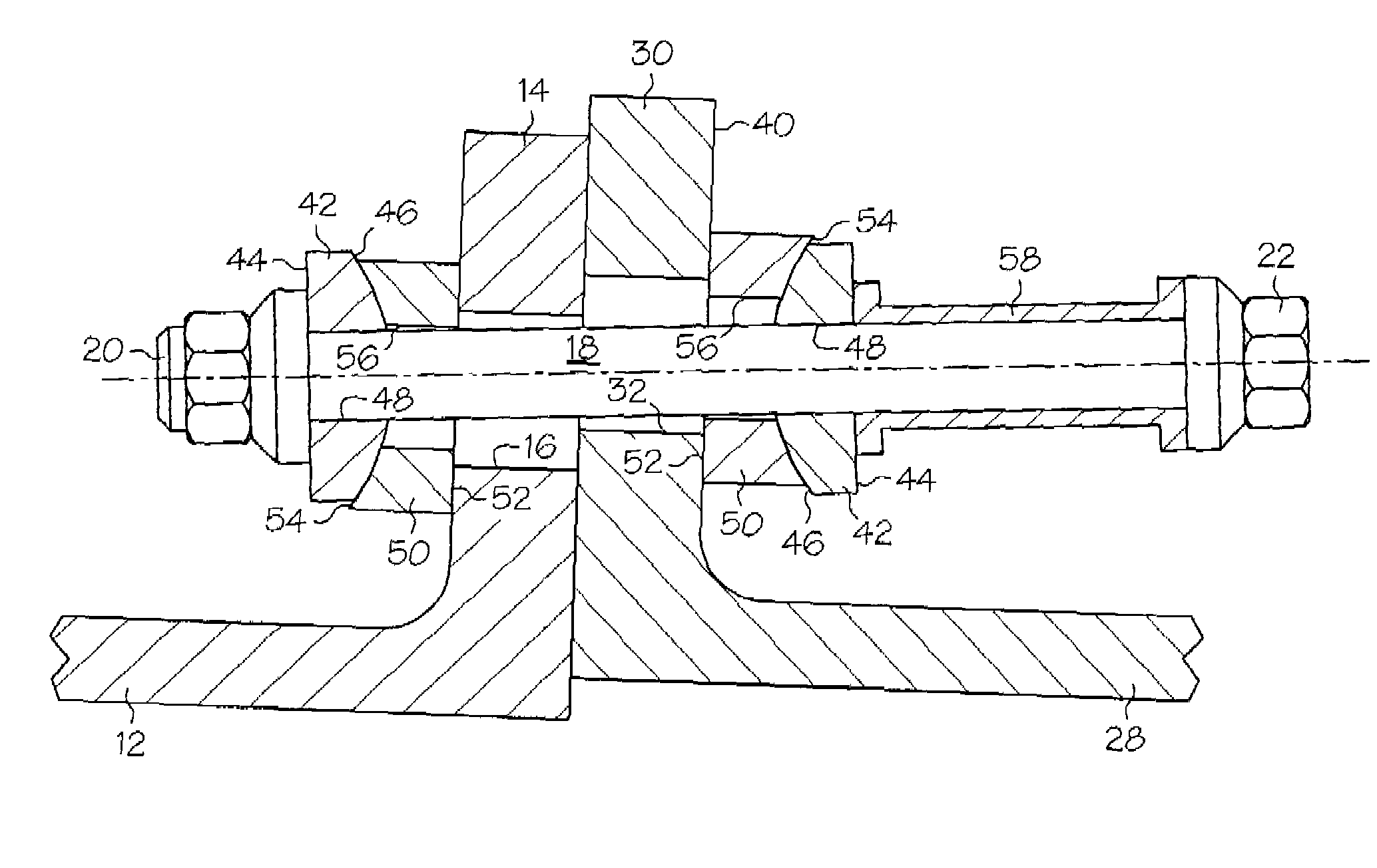
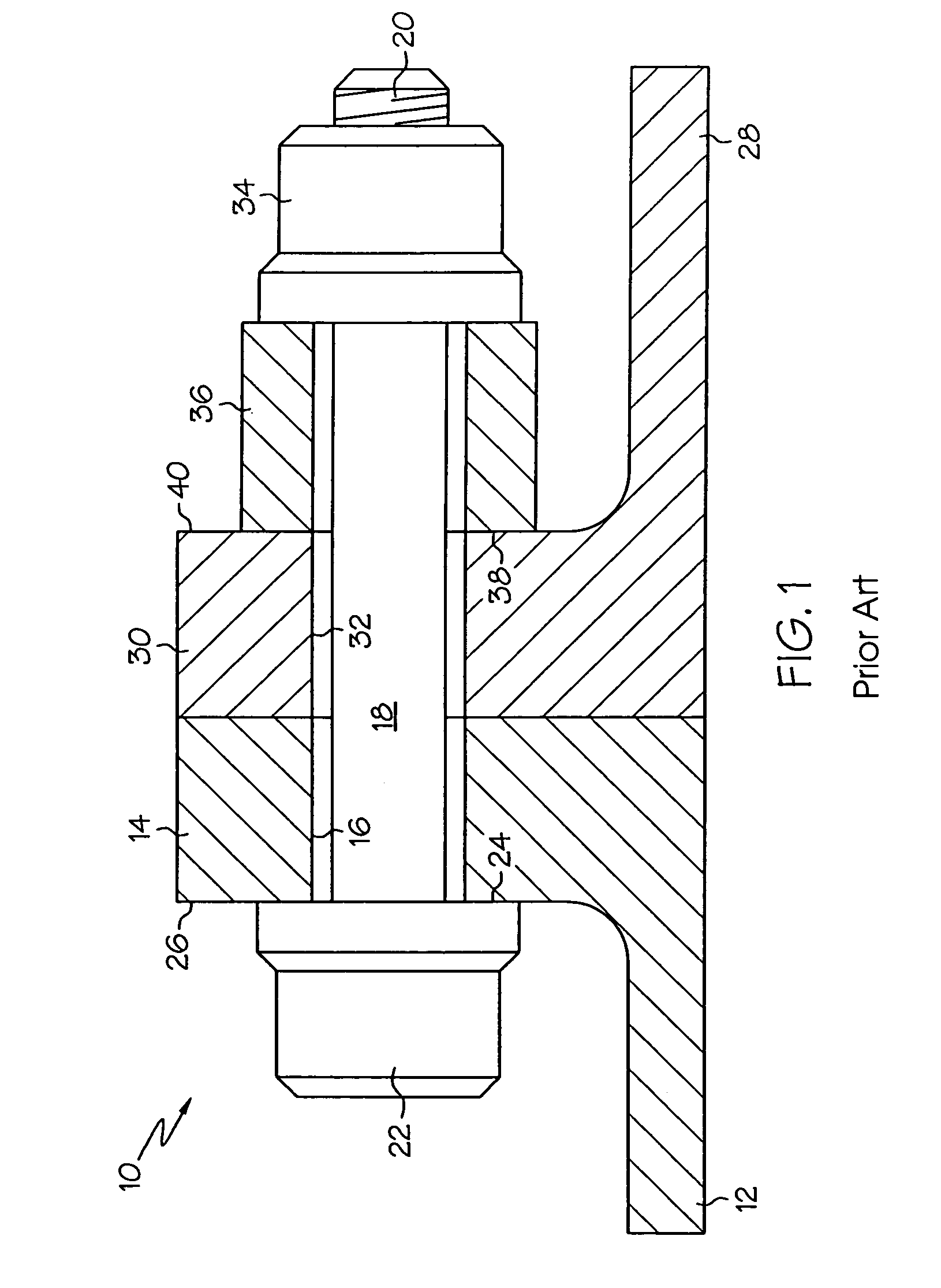
[0009]Referring now to the drawings, and particularly to FIG. 1 thereof, there is shown a conventional bolted connection at a flange joint 10 at which two casing members are connected. A first annular casing has a casing wall 12 that terminates at an outwardly-extending radial flange 14. A plurality of throughbores 16 (only one of which is shown in FIG. 1) is provided in flange 14 for receiving the shank 18 of a connecting bolt 20, which includes a bolt head 22 having an annular bearing face 24 that is in tight contacting engagement with outer surface 26 of flange 14 when bolt 20 is tightened.

[0010]Similarly, a second annular casing has a casing wall 28 that terminates at an outwardly-extending radial flange 30 that includes a plurality of throughbores 32 (only one of which is shown in FIG. 1) for receiving shank 18 of bolt 20. The end of bolt 20 opposite from bolt head 22 receives a connecting nut 34 and an annular spacer 36 so that when bolt 20 and nut 34 are tightened, annular en...


PUM


Abstract

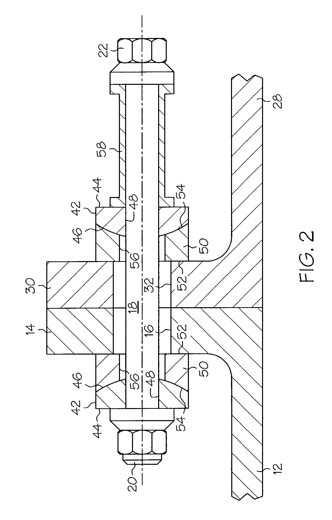
A two-piece washer to allow tilting movement of the washer elements. One annular washer element includes a convex annular surface that engages with a concave annular surface of a second annular washer element. When the convex and concave surfaces of the respective washer elements are placed in face-to-face engagement, the elements of the two-piece washer can pivot relative to each other. When utilized in a bolted connection, such two-piece washers can allow shifting of the bolted components relative to each other without imposing bending loads on the connecting bolt.

Description

BACKGROUND OF THE INVENTION[0001]The present invention relates to bolting arrangements wherein two flanges are bolted together. More particularly, the present invention relates to bolting arrangements in which bolt bending resulting from relative movement of the flanges is minimized.[0002]Flanges are generally bolted together by inserting bolts through bolt holes provided in each of the flanges and that are aligned with each other. Such bolted flanges usually remain in their bolted condition, because a number of connecting bolts are generally provided to securely hold the bolted flanges together. However, the imposition of large radial, tangential, or axial loads on one or both components to which the respective flanges are secured can impose on the connecting bolts bending moments or tensile forces that can cause deformation or rupture of the bolts.[0003]For example, unusual and sometimes large loads can be applied to bolted flanges in turbomachines, where pairs of flanged end casi...

Claims


Application Information

Patent Timeline
Patent Type & Authority Patents(United States)
IPC IPC(8): F16L23/00F16B43/02
CPCF16B43/02Y10T403/645F16B2200/506
Inventor SCHILLING, JAN CHRISTOPHERGUTKNECHT, JAMES EDWARD
Owner GENERAL ELECTRIC CO
Learn More