
VPN router and VPN identification method by using logical channel identifiers

a vpn router and logical channel technology, applied in the field of routers, can solve the problems of inability to identify multiplexed logical channels by vpn identification, increase the networking cost of private lines, and require additional routers

Inactive Publication Date: 2006-05-30
ALAXALA NETWORKS
View PDF14 Cites 37 Cited by
  • Summary
  • Abstract
  • Description
  • Claims
  • Application Information

AI Technical Summary

Benefits of technology

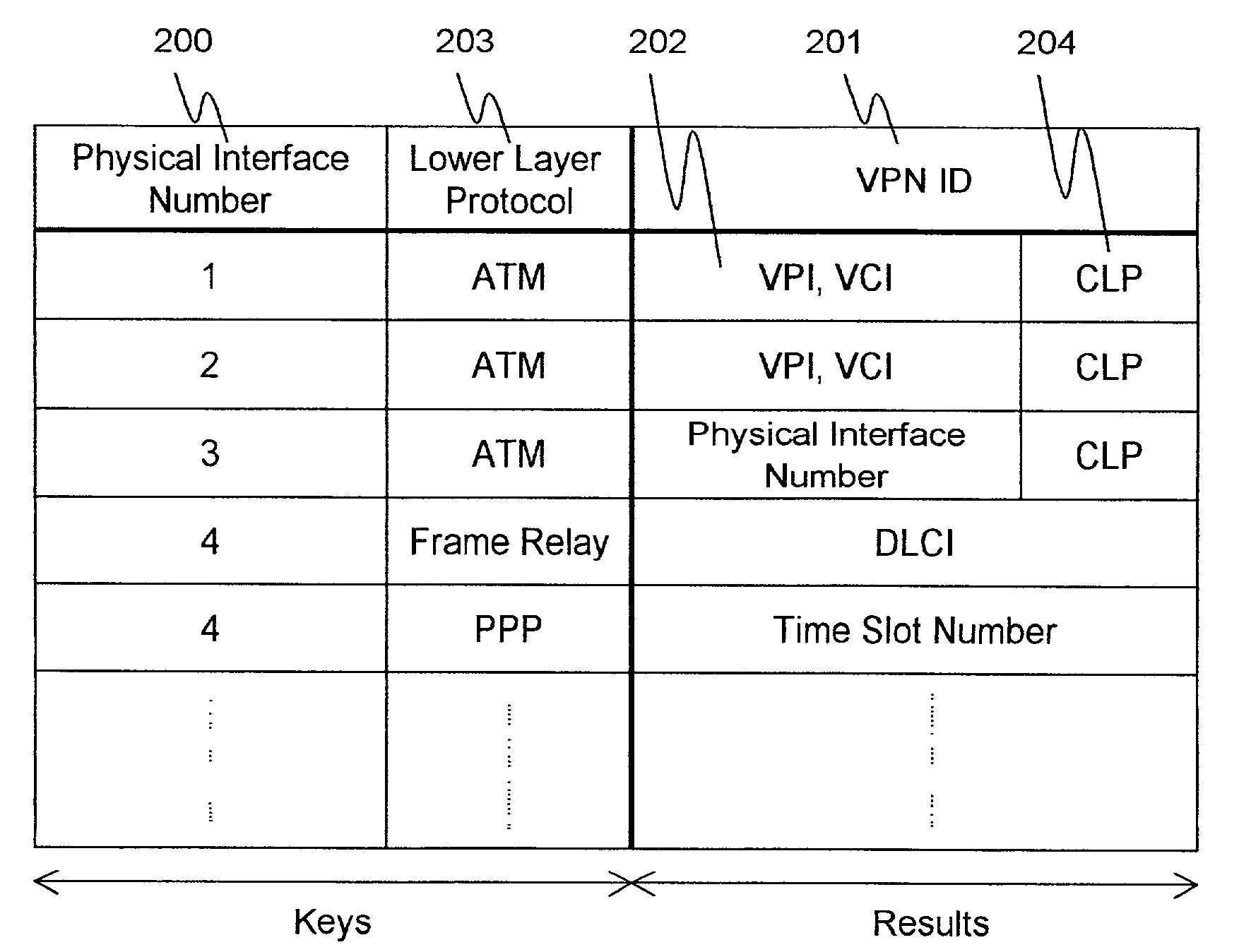
[0016]In the present invention, VPN identification is performed by using the identifiers of logical channels multiplexed and terminated to a physical interface as described above. Therefore, it is not necessary to provide the VPN edge router with physical interfaces corresponding to VPNs interconnected by the router. To connect one corporate network to a plurality of VPNs according to the invention, preparing as many logical channels as the number of VPNs is only required, but preparing as many physical lines as the number of VPNs is not necessary. Even when an ATM network or a frame relay provided by another ISP or carrier is used as intermediate access means from a corporate network to the ISP network that provides VFN service, the present invention enables building a network system having VPNs because the VPNs are identified by their logical channels to the VPN edge router.
[0017]Furthermore, when the router is set up to interconnect VPNs, the present invention allows the ISP network administrator to select a VPN identifier type proper for each VPN-specific lower layer protocol below IP and register it in the VPN ID indication table. Therefore, a network system can be built to comprise VPNs that run under various kinds of lower layer protocols.

Problems solved by technology

This, however, posed a problem that the use of private lines increases the networking cost.
Consequently, a problem arises that expansion of VPNs interconnected by the VPN edge router expands the physical interfaces of the VPN edge router and eventually additional routers are required.
These multiplexed logical channels cannot be identified by VPN identification by physical interface and this is another problem due to the limitation of the previous VPN identification method.

Method used


Image

  • VPN router and VPN identification method by using logical channel identifiers
  • VPN router and VPN identification method by using logical channel identifiers
  • VPN router and VPN identification method by using logical channel identifiers

Examples


Embodiment Construction

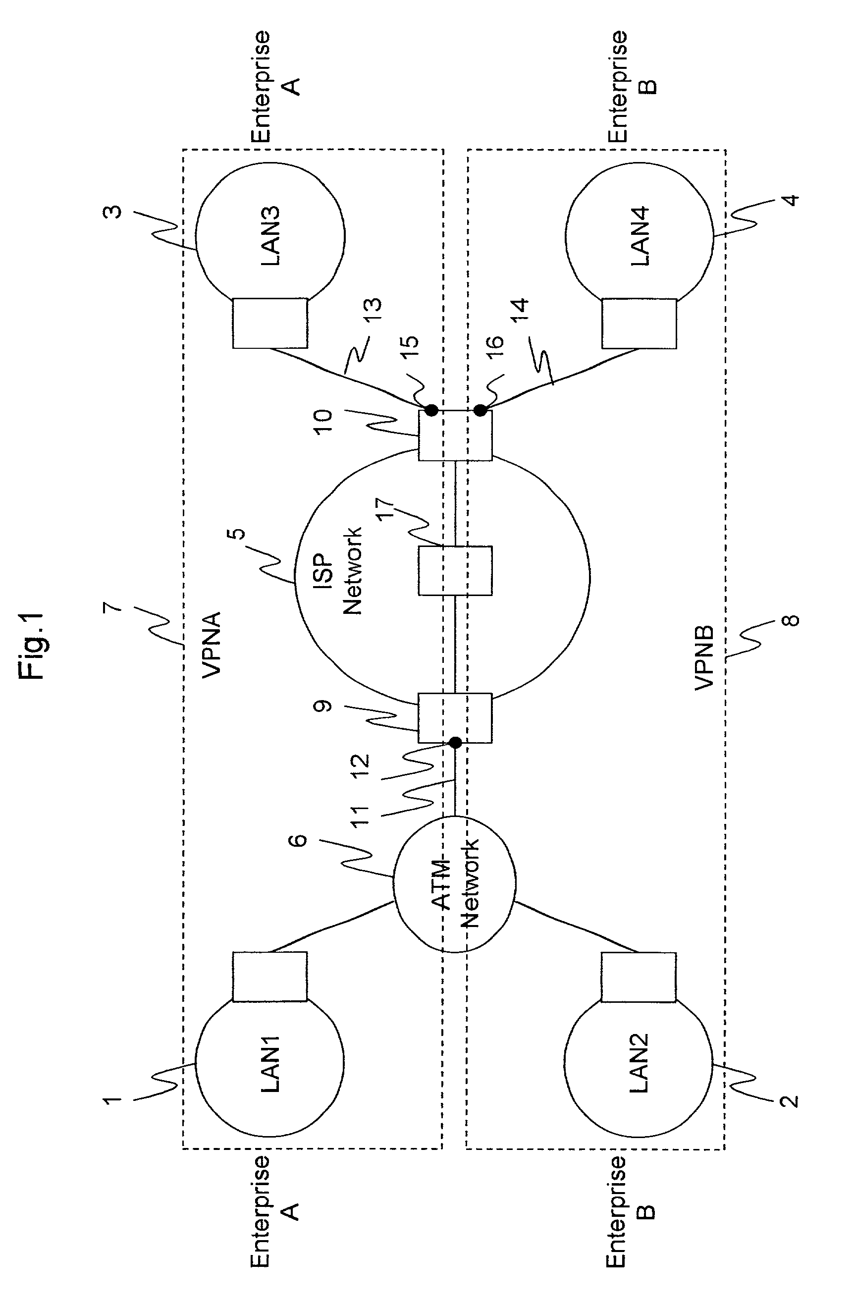
[0034]FIG. 1 is a schematic diagram for explaining a preferred embodiment of forming VPNs interconnected by VPN edge routers according to the present invention. Hereinafter, a lower layer will mean a protocol for encapsulating datagrams in IP packets. Even if an IP header is used to encapsulate datagrams of IP packets, this capsule header will be represented as a lower layer header for convenience.

[0035]An ISP network (5) has edge routers (9 and 10) positioned at the boundaries of the network and a core router (17) positioned in the core of the network. Although a single core router (17) is shown in FIG. 1, the number of core routers is not limited to one. Datagrams are assumed to be encapsulated by MPLS (for ATM) to pass across the ISP network (5), thus implementing reliable data transmission across VPNs. Not only this encapsulation protocol but also other encapsulation protocols mentioned above may be used. The ISP network (5) interconnects LAN1 (1) and LAN2 (2) via the edge route...


PUM


Abstract

A VPN edge router with the ability of identifying VPNs by using the identifiers of logical channels multiplexed on a single input line.

Description

BACKGROUND OF THE INVENTION[0001]1. Field of the Invention[0002]The present invention relates to routers, particularly, a router that interconnects Virtual Private Networks (VPNs) to build a network system via the Internet, a method of packet forwarding control to be used on the router, and a method of registering routing and related settings with the router.[0003]2. Description of Related Art[0004]When networking a plurality of intra-corporation networks existing in different areas, corporations conventionally used private lines to interconnect these networks, thus forming a network system that is isolated from external networks (to ensure network security). This, however, posed a problem that the use of private lines increases the networking cost. As a result, along with the prevalence of the Internet that can be used at a low charge, there have been increasing needs for an art of forming a low-cost Virtual Private Network (hereinafter referred to as VPN) by using the Internet. Th...

Claims


Application Information

Patent Timeline
Patent Type & Authority Patents(United States)
IPC IPC(8): H04L12/28H04L12/56H04L12/46H04L45/74
CPCH04L12/4608H04L12/4641H04L45/04H04L2012/5669H04L2012/5621H04L2012/5665
Inventor AKAHANE, SHINICHISAKAMOTO, KENICHISUGAI, KAZUO
Owner ALAXALA NETWORKS
Learn More