
Self-identifying cable for interconnecting electronic devices

Inactive Publication Date: 2006-05-23
AVAYA INC
View PDF3 Cites 151 Cited by
  • Summary
  • Abstract
  • Description
  • Claims
  • Application Information

AI Technical Summary

Benefits of technology

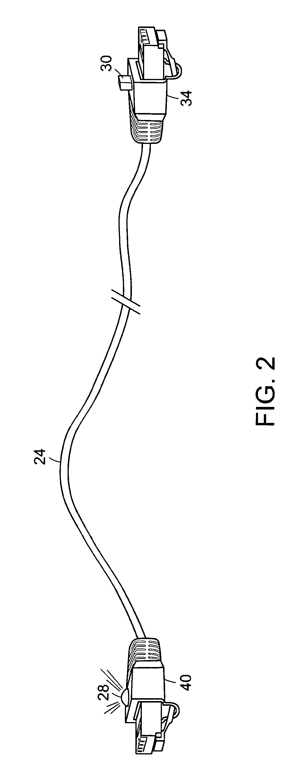
[0003]In accordance with the principles of the invention, there is provided apparatus for use with a cable for interconnecting electronic devices. The apparatus includes an indicator associated with a cable for identifying a characteristic of the cable, and includes a mechanism operable to cause the indicator to identify the characteristic of the cable. The characteristic identified can be the location of one end of the cable. According to an aspect of the invention, the indicator is an LED located on one end of the cable. The mechanism is a pushbutton located at the other end of the cable. The LED is illuminated when the pushbutton is activated. A signal generator is responsive to the pushbutton and provides a signal to the LED to cause the LED to illuminate. The signal generator may conveniently be implemented as a DTMF encoder.
[0008]All of the variations of the invention herein described are advantageous to locate cable ends without disrupting network connectivity or causing undue manual searching.

Problems solved by technology

As users move, or network equipment is upgraded or replaced, the cables tend to become entangled.
It becomes very difficult to identify the locations of cable ends.
For instance, when a cable is plugged into a port on the network equipment, it is difficult to determine where on the patch panel the other end of the cable resides.
If not, it means the equipment in the user's office is not connected or not powered up.
When successful, this first technique disadvantageously causes the momentary disruption of network connectivity.
The problem is exacerbated when many cables run through a constricted opening, or are tightly bound together with a cable-strap.

Method used


Image

  • Self-identifying cable for interconnecting electronic devices
  • Self-identifying cable for interconnecting electronic devices
  • Self-identifying cable for interconnecting electronic devices

Examples


Embodiment Construction

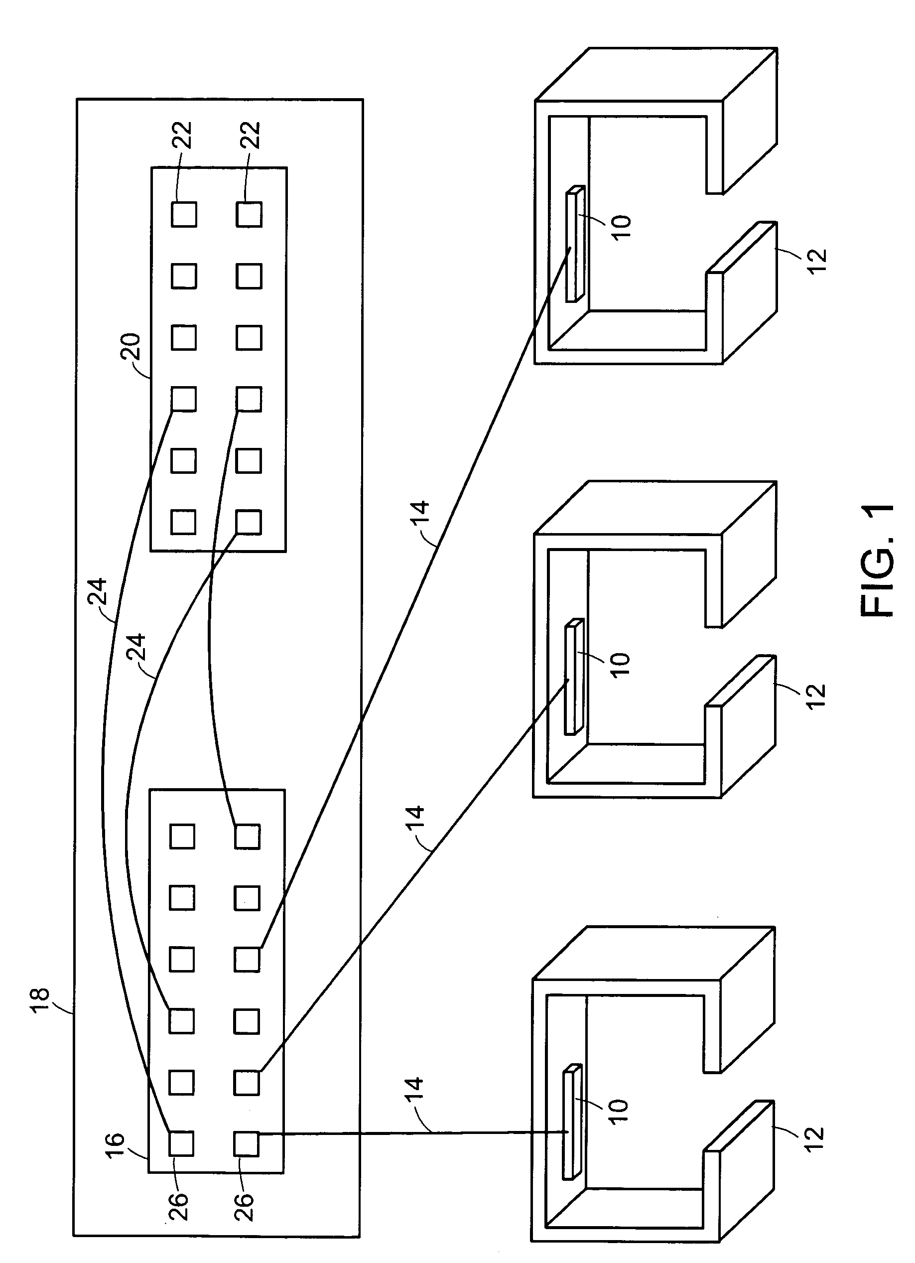
[0024]In FIG. 1 there is shown a typical office environment wherein network devices 10 in offices or cubicles 12 are connected by cables 14 to a patch panel 16 located in a wiring closet 18. The wiring closet 18 also includes racks of network equipment 20. The ports 22 on the network equipment 20 are connected via cables 24 to ports 26 on the patch panel 16, thereby establishing network connectivity between the network equipment 20 and the network devices 10. The network devices 10 may be for example computer network adapters, IP telephones, and the like. The network equipment 20 may be for example routers, Ethernet switches, and the like. A given wiring closet 18 may contain patch panels 16 and network equipment 20 having hundreds of ports, thus requiring hundreds of cables 24.

[0025]The network equipment 20 and network devices 10 are preferably Ethernet devices that conform to the IEEE 802.3af standard, currently described in IEEE Draft 802.3af / D3.0, herein incorporated by referenc...


PUM


Abstract

Apparatus for use with a cable for interconnecting electronic devices is described. The apparatus includes an indicator for identifying a characteristic of the cable, and includes a mechanism operable to cause the indicator to identify the characteristic of the cable. The indicator can be for example an LED and can be used to identify the location of an end of the cable. The mechanism can be a pushbutton located at the other end of the cable. The LED is illuminated when the pushbutton is activated. A signal generator is responsive to the pushbutton and provides a signal to the LED to cause the LED to illuminate. The signal generator can be implemented with a DMTF encoder.

Description

FIELD OF THE INVENTION[0001]The present invention relates generally to cables for interconnecting electronic devices, and more particularly to mechanisms for identifying characteristics of such cables.BACKGROUND OF THE INVENTION[0002]Many of today's corporations have large data network infrastructures. A typical office building data closet has a patch-panel containing many connectors for network cables that run to the offices and cubicles elsewhere in the building. Network equipment often sits in a nearby rack. Network cables connect each of the office ports to one of the ports on the network equipment through the patch-panel. As users move, or network equipment is upgraded or replaced, the cables tend to become entangled. It becomes very difficult to identify the locations of cable ends. For instance, when a cable is plugged into a port on the network equipment, it is difficult to determine where on the patch panel the other end of the cable resides. In order to determine which net...

Claims


Application Information

Patent Timeline
IPC IPC(8): G05B11/01
CPCH01R13/641H01R13/7175H01R13/717H01R13/6691
Inventor ZWEIG, JONATHAN M.ALLEM, JOSEPH M.
Owner AVAYA INC
Learn More