Paper-making machine wire cloth

a paper-making machine and wire cloth technology, applied in the field of paper-making machines, can solve the problems of affecting the service life the bowing of the covering of the wire cloth, and the internal wear of the composite fabric, and achieve the effects of cost-effective production, long service life and same quality scal

Inactive Publication Date: 2006-05-23
ANDRITZ TECH & ASSET MANAGEMENT
View PDF10 Cites 14 Cited by
  • Summary
  • Abstract
  • Description
  • Claims
  • Application Information

AI Technical Summary

Benefits of technology

[0007]Objects of the present invention are to provide improved paper making machine wire cloths having longer service lives with the same quality scales for paper manufacture and being cost effective in production.
[0008]These objects are basically attained by a paper making machine wire cloth having at least one part of each backing side warp thread positioned at a point at which this warp thread is above at least one associated backing side weft thread. That one part changes to the paper side, extends over the following paper side weft thread, and then returns to the backing side. A paper side free of marking is achieved in the case of linen weave, along with improvement in the surface uniformity. In addition, a compact bond of the individual fabrics without additional binding threads is obtained in this way. Separation of the layers of the individual fabrics or shifting of these layers relative to each other is largely excluded. Consequently, long service lives accompanied by high production quality can be achieved in paper production by the paper making machine wire cloth of the present invention. Production of the paper making machine wire cloth cost effective, as well.
[0009]One preferred embodiment of the paper making machine wire cloth of the present invention is characterized in that a minimum of four associated backing side weft threads support the change position in the area of change of the backing side warp thread from the backing side to the paper side and from the paper side back to the backing side. Something may be used on the backing side of the weft threads, which result in high transverse stability within the fabric bond and form a corresponding volume of abrasion, to increase the service life of the paper making machine wire cloth. Preferably, the linen weave is designed as a longer floating weave to improve the surface uniformity in paper production.
[0010]In one especially preferred embodiment of the paper making machine wire cloth of the present invention, a backing side weft thread is mounted between the four backing side weft threads making up a first group and a second group with two backing side weft threads in the direction of the paper side warp thread above a backing side warp thread. This backing side weft thread supports a paper side weft thread over which the paper side warp thread is guided. The support points thus formed yield a high degree of stability in relation to the two individual fabric layers of the wire cloth under consideration.

Problems solved by technology

This arrangement results in rapidly changing bowing of the covering of the wire cloths in the longitudinal direction.
The internal wear of a composite fabric is due particularly to the circumstance that the individual cloth fabric layers are stretched or buckled to a varying extent during reversals of the wire cloth, as occur in the area of guide rollers or wire section over which the composite cloth is guided.
When suitable high stresses occur, the possibility exists that the thin binding threads will split and the connection between the cloth fabrics will be lost.
However, undesirable stiffening of the fabric results from the accumulation itself of the intersections in the transverse direction.
These differences may in turn be expressed in differences in tension, with the result that the binding threads specific to the cloth may also break and may result in failure of the conventional paper making machine wire cloth.
This limitation reduces the possibility of effective support on the backing side.
Production of the conventional composite fabrics as described is also costly.

Method used


Image

  • Paper-making machine wire cloth
  • Paper-making machine wire cloth
  • Paper-making machine wire cloth

Examples


Embodiment Construction

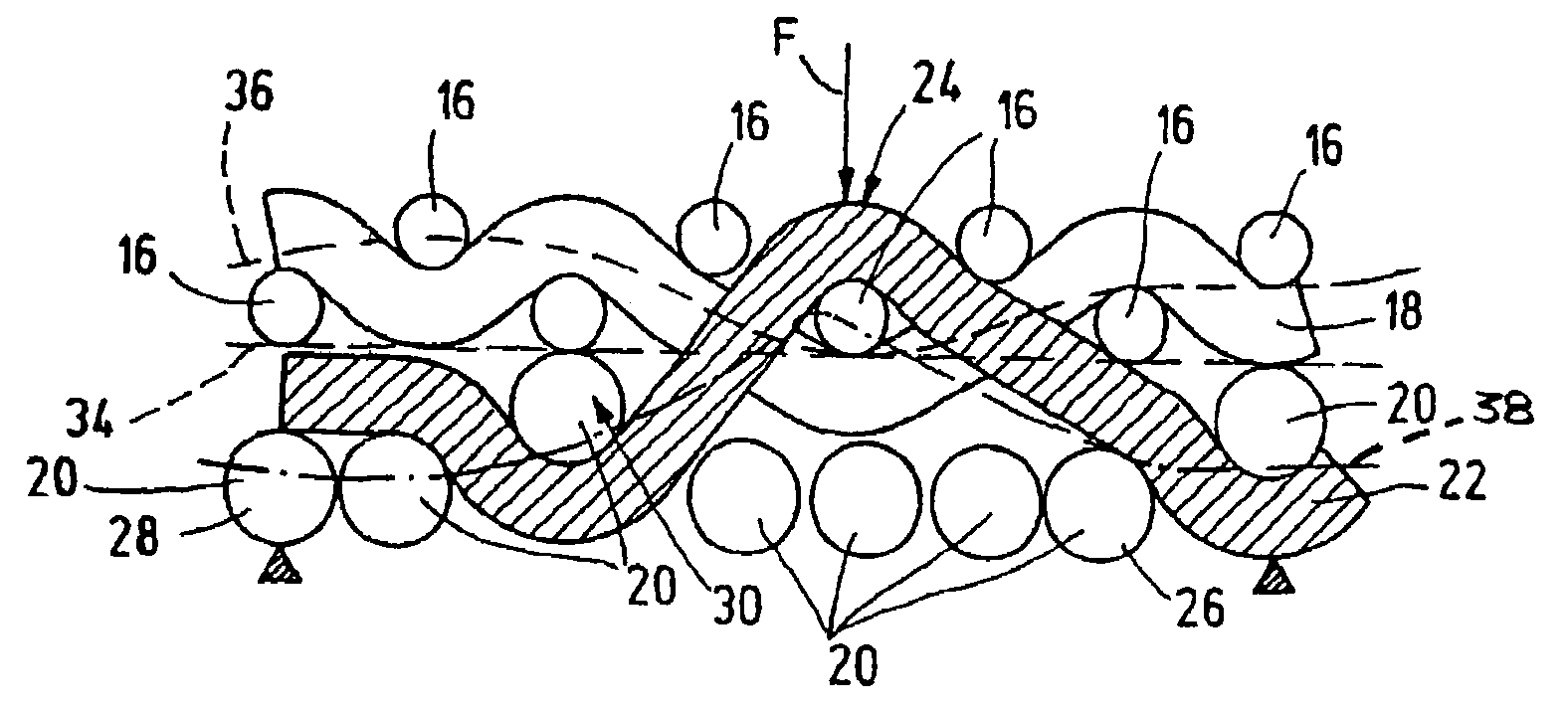
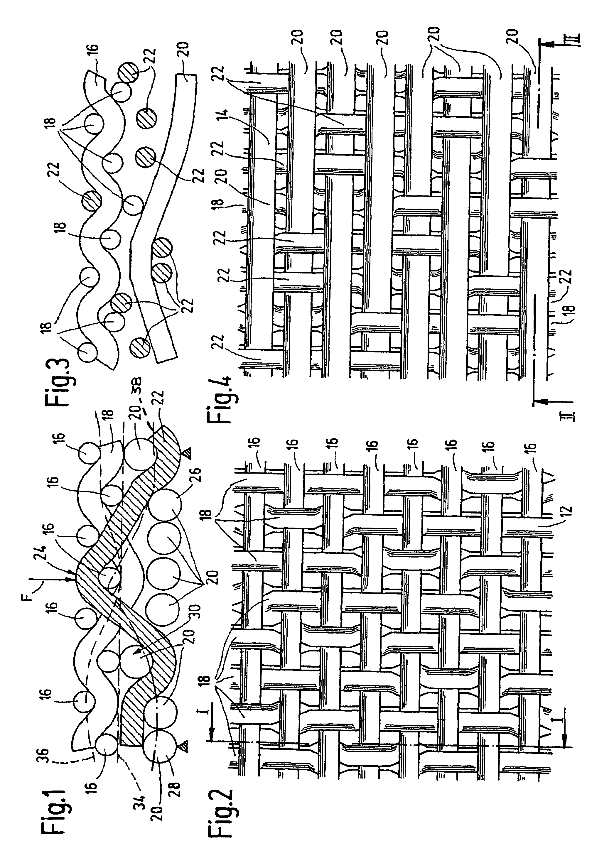
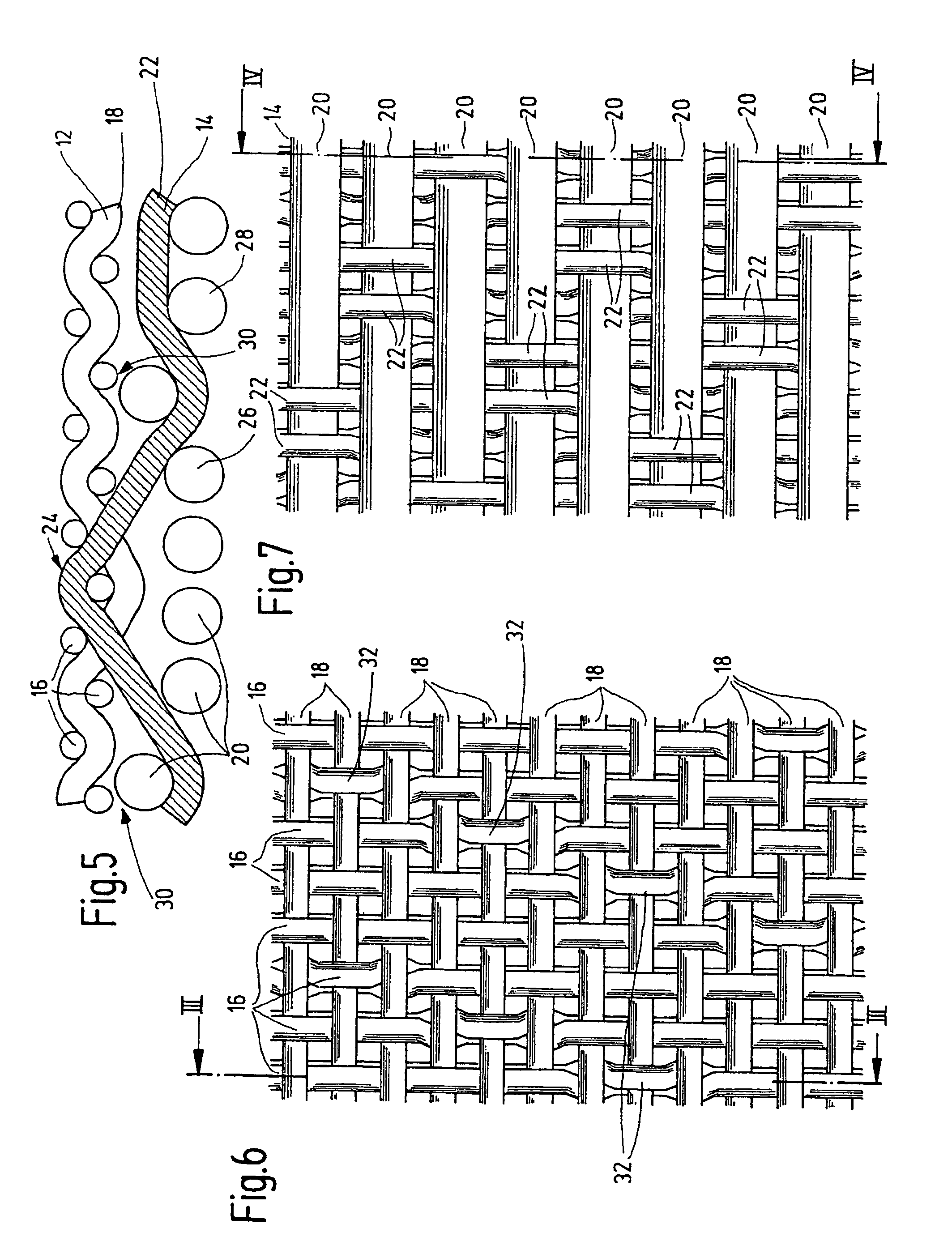
[0022]The figures described above show to some extent differing embodiments of portions of cloth fabrics for a paper making machine wire cloth. The wire cloth may be used in particular for the so-called sheet-forming zone in conventional paper manufacturing machines. The cloth fabric if formed of an individual fabric for the paper side 12 and an individual fabric for the backing side 14. The paper side 12 includes a set of weft threads 16 and warp threads 18. The backing side 14 as well includes of a set of weft threads 20 and warp threads 22. As seen particularly in FIGS. 8, 9, and 10, the paper side warp threads 18 and the associated weft threads 16 together form a linen weave. Also as illustrated, the diameters and the number of the paper side and backing side warp threads 18, 22 are more or less the same (i.e., are substantially equal). The backing side warp thread 22 moves at a change point, identified as a whole by 24, from the backing side 14 to the paper side 12 and then ret...


PUM


Abstract

A paper-making machine wire cloth has an individual woven cloth for the paper side (12) and an individual woven cloth for the running side (14). Each woven cloth includes a set of weft threads (16;20) and warp threads (18;22). The diameters and the number of paper side and running side warp threads (18;22) are essentially equal. The paper side warp threads (18) and weft threads (16), together, form a weave. At least a portion of the running side threads (22) passes into the paper side (12), extends over the subsequent paper side weft thread (16) and, afterwards, returns to the running side (14) each time at a location (24), at which this warp thread (22) is located above at least one assigned running side weft thread (20). A marking-free paper side is achieved in the weave, while simultaneously improving the surface uniformity. A compact binding of the individual woven cloth is effected without the use of additional binding threads, largely avoiding a layer separation of the individual woven cloth or an offset of the same with regard to one another.

Description

FIELD OF THE INVENTION[0001]The present invention relates to a paper making machine wire cloth formed of an individual fabric for the paper side and an individual fabric for the backing side. Each fabric has one set of weft threads and warp threads. The diameter and the number of the paper side and backing side warp threads are more or less equal. The paper side warp threads and weft threads together form a linen weave.BACKGROUND OF THE INVENTION[0002]In the paper manufacturing industry, an increasing number of high-capacity paper machines with speeds of up to 2,000 m / min and operating widths exceeding 10 m are used. As a general rule, the sheet forming unit is configured as a double-cloth former, and in many cases, as a split former. In such machines, the sheet forming process takes place immediately between two paper making cloths in a relatively short drainage zone. Because of this short distance and the high production speed, the time for sheet forming is reduced to a few millis...

Claims


Application Information

Patent Timeline
IPC IPC(8): D21F1/10D03D3/02D03D11/00D21F1/00
CPCD03D11/00D21F1/0045Y10S162/903
Inventor HEGER, WOLFGANGFICHTER, KLAUS
Owner ANDRITZ TECH & ASSET MANAGEMENT
Why Eureka
Try Eureka