Eureka AIR delivers breakthrough ideas for toughest innovation challenges, trusted by R&D personnel around the world.

Method and apparatus for securing a suture

a technology for securing sutures and sutures, which is applied in the direction of snap fasteners, shoelace fastenings, buckles, etc., can solve the problems of reducing the overall force transmitting capability of the suture, tying a knot is difficult, and the difficulty of securing sutures relative to body tissu

Inactive Publication Date: 2006-05-23
BONUTTI 2003 TRUST A THE +1
View PDF24 Cites 235 Cited by
  • Summary
  • Abstract
  • Description
  • Claims
  • Application Information

AI Technical Summary

Benefits of technology

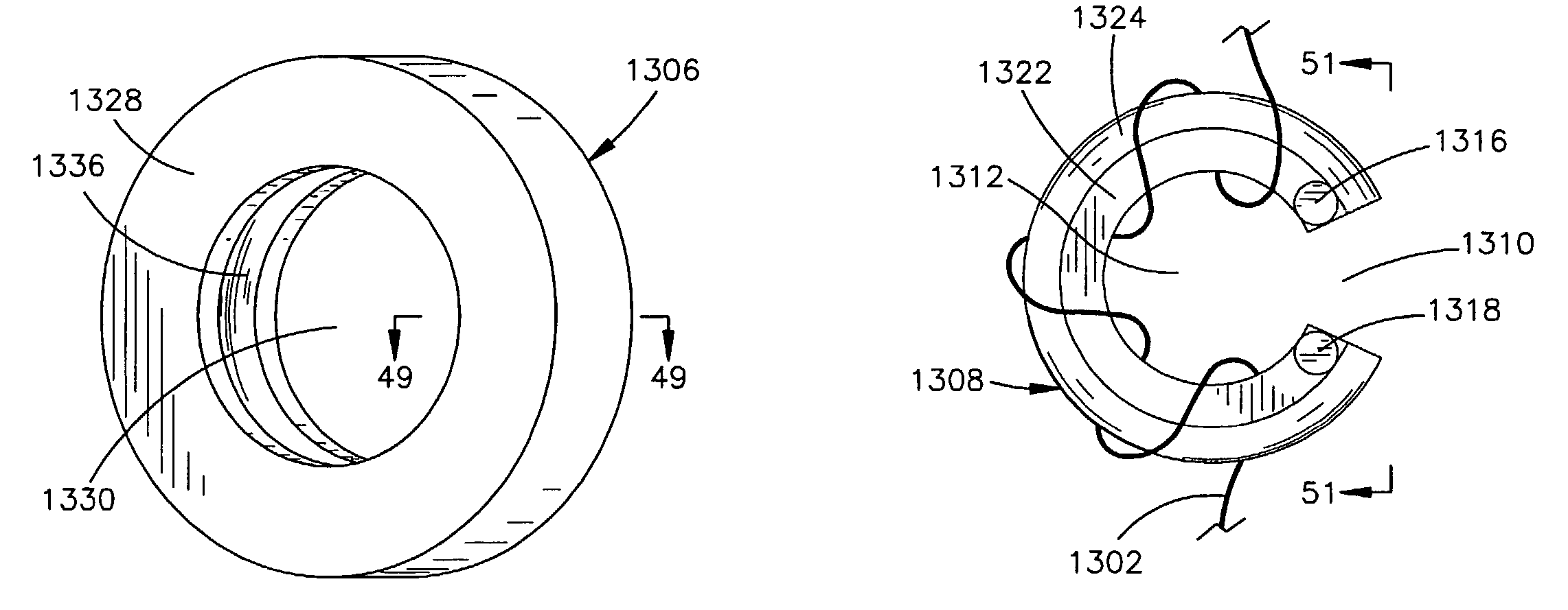
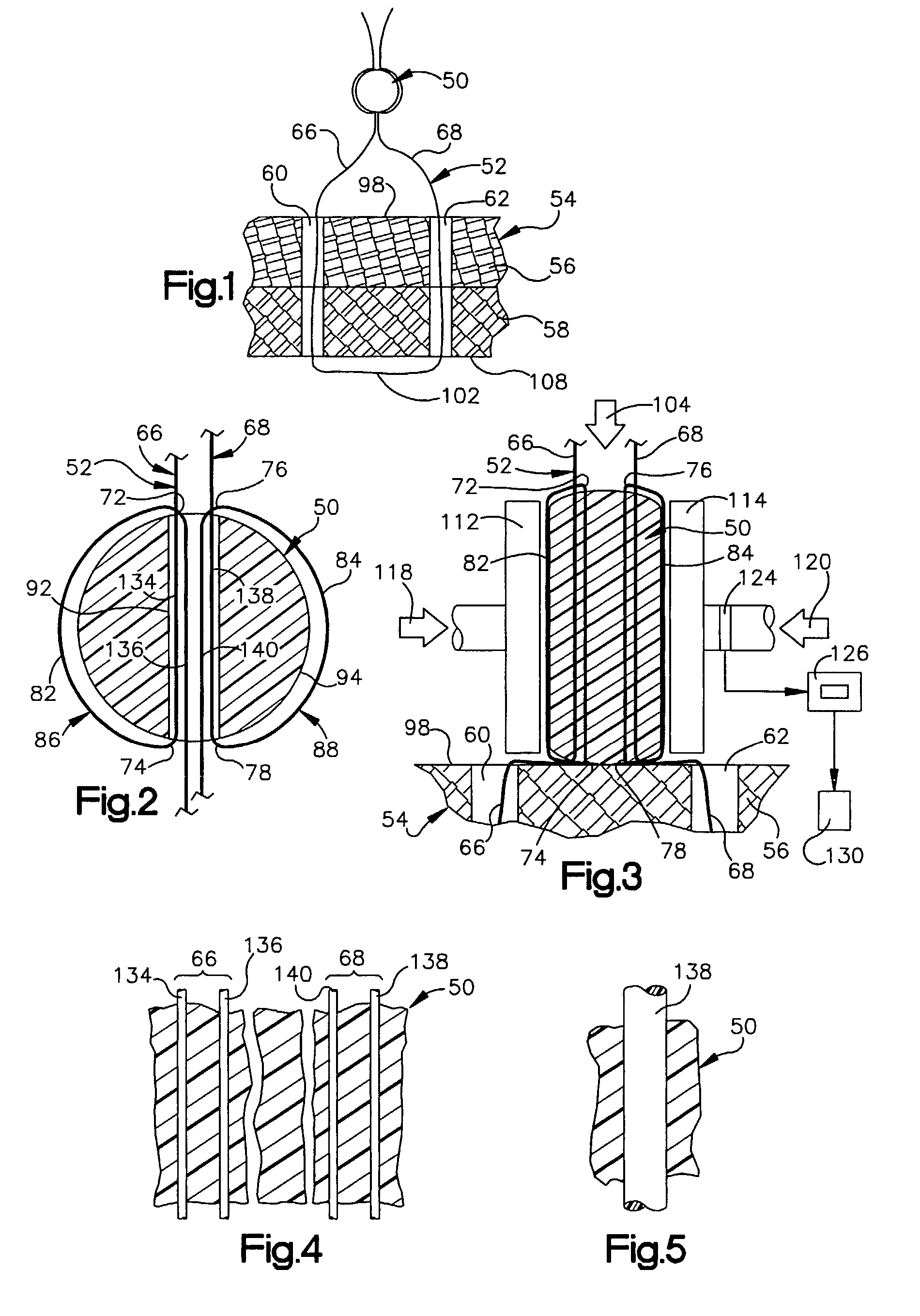
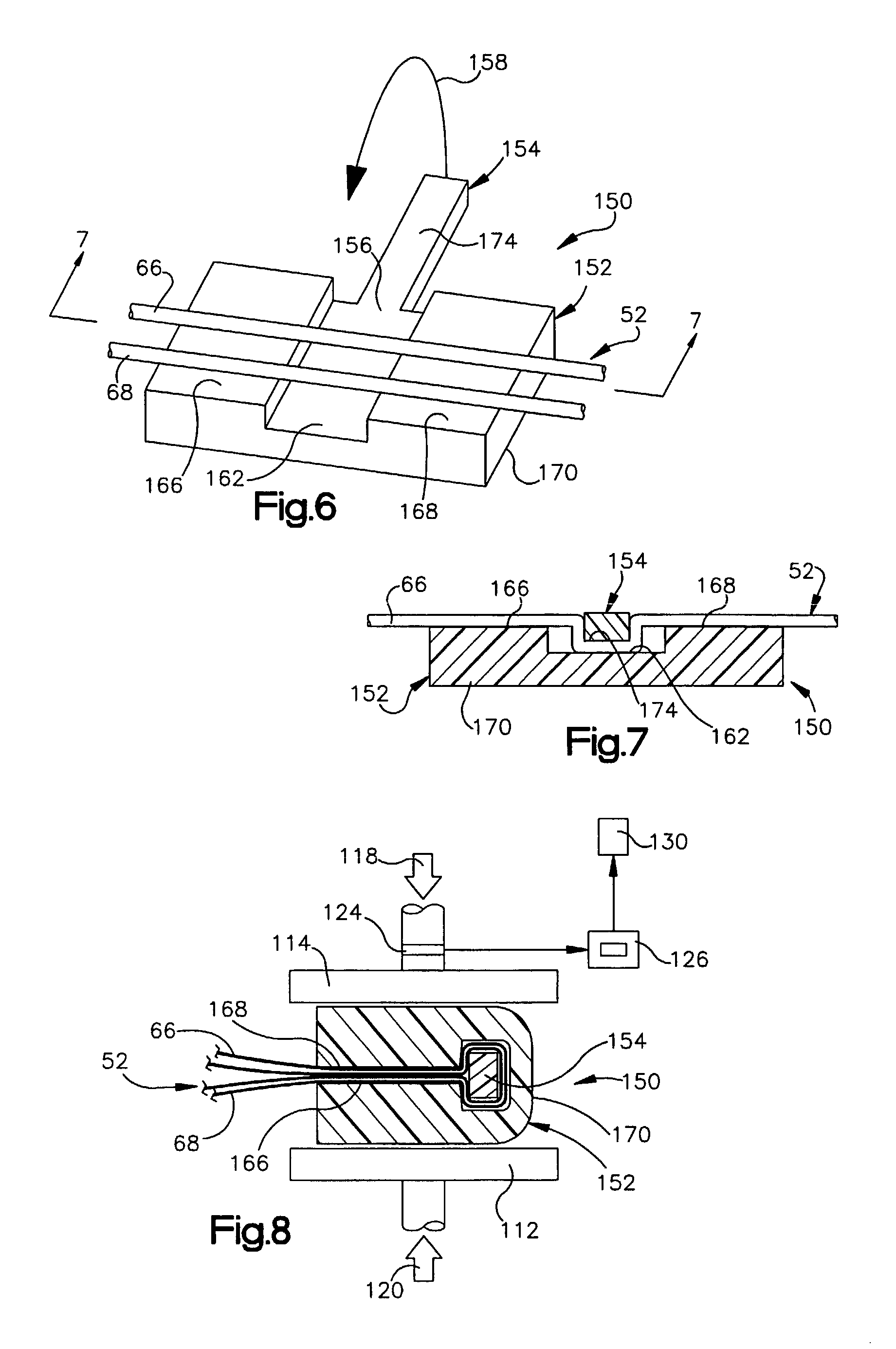
[0005]The present invention provides a new improved method and apparatus for use of securing a suture relative to body tissue. A portion of the suture is enclosed with a first member. Although the first member may have many different configurations, in one embodiment of the invention, the first member has a tubular configuration. The first member is moved along the suture toward the body tissue with the suture extending through a passage in the first member. The first member is then deformed to change the configuration of the first member. The first member may be deformed by bending the first member to grip the suture which extends through the passage in the first member. The first member is retained in the bent configuration by a holder.

Problems solved by technology

Difficulty has been encountered in securing sutures against movement relative to body tissue.
However, the knot weakens a portion of the suture and reduces the overall force transmitting capability of the suture.
In addition, a suture which is held by a knot applies force to a relatively small area of the body tissue and tends to cut or separate the body tissue.
Many operations are conducted in very restricted space where the tying of a knot is difficult.

Method used


Image

  • Method and apparatus for securing a suture
  • Method and apparatus for securing a suture
  • Method and apparatus for securing a suture

Examples


embodiment

of FIG. 20

[0179]In the embodiment of the invention illustrated in FIGS. 17–19, the cylinder 316 is rotatable relative to the housing 314. In the embodiment of the invention illustrated in FIG. 20, cylinders are fixedly connected with the housing. Since the embodiment of the invention illustrated in FIG. 20 is similar to the embodiment of the invention illustrated in FIGS. 17–19, similar terminology will be utilized to identify similar components. It should be understood that one or more features of the embodiments of the invention illustrated in FIGS. 1–19 may be used with the embodiment of the invention illustrated in FIG. 20.

[0180]A suture retainer 356 includes a rectangular housing 358 which encloses a plurality of cylinders 360, 362, 364 and 366. The cylinders 360–366 have parallel central axes which extend parallel to flat rectangular upper and lower side walls 370 and 372 of the housing 358. Opposite end portions of the cylinders 360–366 are fixedly connected with rectangular ...


PUM


Abstract

An improved method and apparatus is provided to secure a suture relative to body tissue. When a predetermined minimum force is being transmitted between a suture retainer and the body tissue, the suture is gripped with the suture retainer by plastically deforming material of the suture retainer. One or more bends may be formed in suture by the suture retainer to increase the holding action between the suture retainer and the suture. The bends in the suture may be formed by wrapping the suture around a portion of the suture retainer. During movement of the suture retainer toward the body tissue, the bends may be moved along the suture. One or more bends may be formed in the suture by bending a tubular member through which the suture extends. The tubular member may be maintained in a bent condition by a C-shaped holder member. Alternatively, the tubular member may be maintained in a bent condition by members which are latched together.

Description

RELATED APPLICATION[0001]This application is a divisional of U.S. patent application Ser. No. 09 / 523,442 filed Mar. 10, 2000 now U.S. Pat. No. 6,475,230. This application is also a continuation-in-part of U.S. patent application Ser. No. 09 / 348,940 filed Jul. 7, 1999 by Peter M. Bonutti, Matthew J. Cremens, and Ping Liu (now U.S. Pat. No. 6,159,234). The aforementioned U.S. patent application Ser. No. 09 / 348,940 is itself as continuation-in-part of U.S. patent application Ser. No. 08 / 905,084 filed Aug. 1, 1997 by Peter M. Bonutti, Matthew J. Cremens, and Ping Liu (now U.S. Pat. No. 6,010,525). The benefit of the earlier filing dates of the aforementioned application Ser. Nos. 09 / 523,442; 09 / 348,940 and 08 / 905,084 is claimed for all material common to this application and the aforementioned applications.BACKGROUND OF THE INVENTION[0002]The present invention relates to a new and improved method and apparatus for securing a suture against movement relative to body tissue by using a ret...

Claims


Application Information

Patent Timeline
Patent Type & Authority Patents(United States)
IPC IPC(8): A61B17/04
CPCA61B17/0487A61B17/0401Y10T24/3907A61B2017/045A61B2017/0453A61B2017/0454A61B2017/0456A61B2017/0458A61B2017/0464A61B2017/0488A61B2017/0496A61B2017/0619Y10T24/3969Y10T24/3973A61B2017/0445
Inventor BONUTTI, PETER M.CREMENS, MATTHEW J.LIU, PING
Owner BONUTTI 2003 TRUST A THE
Why Eureka
Eureka Blog
Learn More