
Multi-mode microresistivity tool in boreholes drilled with conductive mud

a multi-mode, micro-resistivity technology, applied in the direction of measurement devices, scientific instruments, instruments, etc., can solve the problems of rxo measurement from an msfl device having 100% or even larger error, msfl measurement in highly resistive formation less reliable, and tool sensitive to the presence of mudcake or standoff

Active Publication Date: 2006-05-16
HALLIBURTON ENERGY SERVICES INC
View PDF5 Cites 73 Cited by
  • Summary
  • Abstract
  • Description
  • Claims
  • Application Information

AI Technical Summary

Benefits of technology

The patent text describes a method for measuring the resistivity of the flushed zone in a wellbore during drilling operations. This method is important for accurately estimating the movability of formation hydrocarbon. The text describes a device called the Micro Spherically Focused Log (MSFL) which can provide a shallow measurement into formation behind the borehole wall. However, the effectiveness of this device is limited when the resistivity ratio between the formation and the mud is high. The patent proposes a new device that can overcome this limitation and provide a reliable measurement of flushed zone resistivity.

Problems solved by technology

But if this ratio is high, e.g. greater than 10,000, the tool becomes sensitive to the presence of mudcake or standoff effect.
Under this situation, the Rxo measurement from an MSFL device may have 100% or even larger error.
This has made MSFL measurement in highly resistive formation less reliable.

Method used


Image

  • Multi-mode microresistivity tool in boreholes drilled with conductive mud
  • Multi-mode microresistivity tool in boreholes drilled with conductive mud
  • Multi-mode microresistivity tool in boreholes drilled with conductive mud

Examples


Embodiment Construction

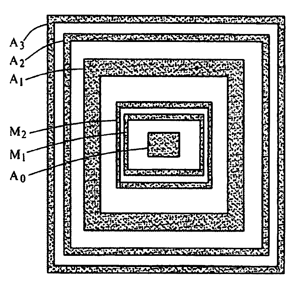
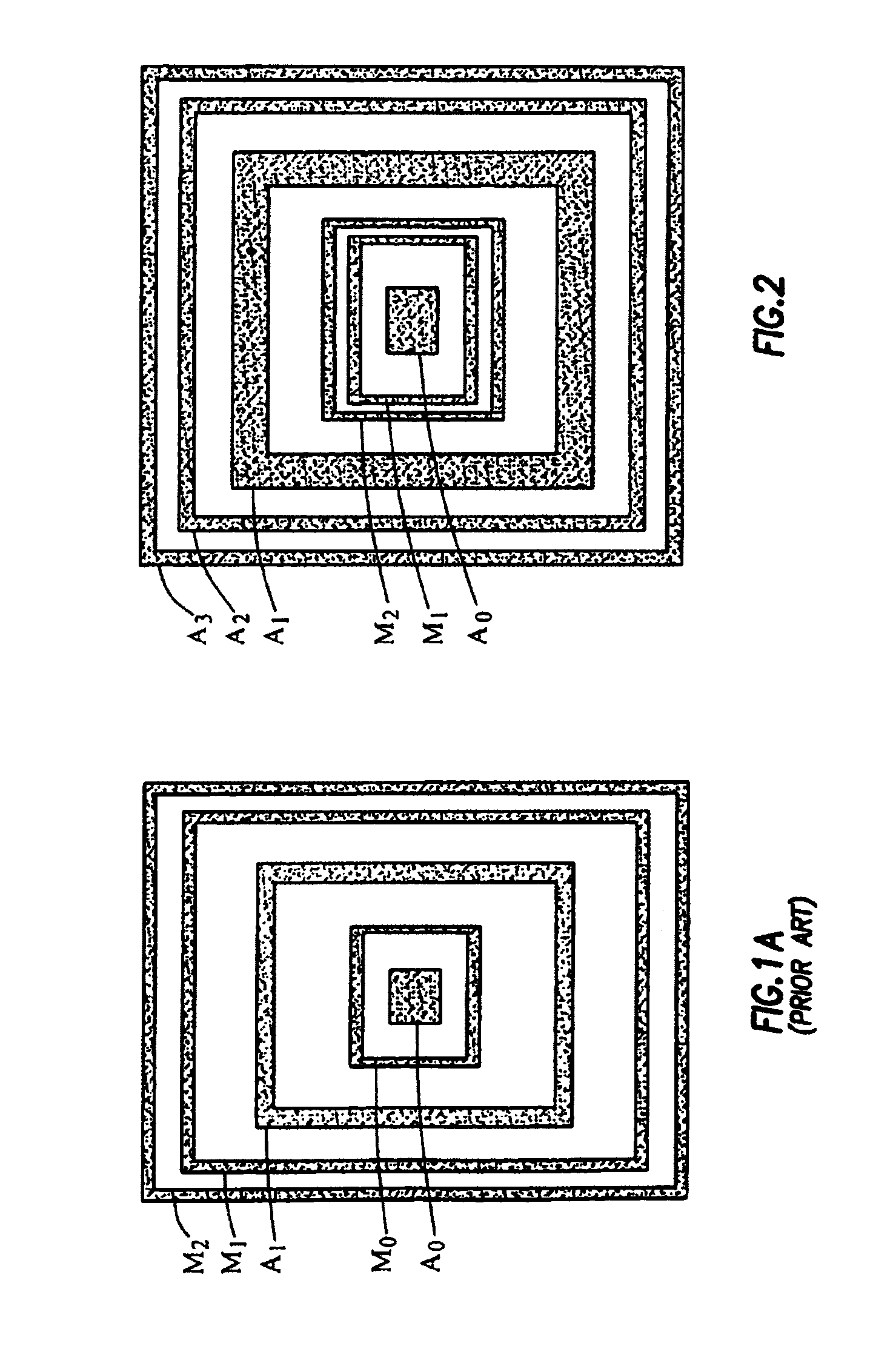
[0027]One aspect of this invention includes a tool that provides multiple microresistivity measurements into the near-borehole environment. A great deal of information is retrieved by the tool regarding the flushed zone, and an accurate flushed-zone resistivity (Rxo) value can be obtained. Mudcake thickness and its resistivity, as well as standoff distance, may also be provided.

[0028]A microresistivity tool design according to one embodiment of the invention is illustrated in FIG. 2. The microresistivity tool shown in FIG. 2 includes six concentric electrode rings. These rings are not limited to the rectangular shapes of FIG. 2, but may be of any suitable geometry. FIG. 2A illustrates a series of six linearly arranged electrodes labeled A0, M1, M2, A1, A2, and A3 that would operate in an analogous manner to the resistivity tool with concentric electrodes as hereinafter described.

[0029]Referring back to FIG. 2, with reference to the electrodes from the center and moving outside, elec...


PUM


Abstract

A multi-mode resistivity tool measures at multiple depths into the near-borehole formation. By use of a four mode tool, measuring to four depths at the formation, a more accurate invasion zone resistivity measurement may be made than previously known. The tool itself is shown as including six concentric electrodes, although not every electrode is necessary for every mode.

Description

CROSS-REFERENCE TO RELATED APPLICATIONS[0001]Not Applicable.STATEMENT REGARDING FEDERALLY SPONSORED RESEARCH OR DEVELOPMENT[0002]Not Applicable.BACKGROUND OF THE INVENTION[0003]In drilling a borehole in the earth, such as for the recovery of hydrocarbons or for other applications, it is conventional practice to connect a drill bit on the lower end of an assembly of drill pipe sections which are connected end-to-end so as to form a “drill string.”FIG. 1 includes a drilling installation having a drilling rig 10 at the surface 12 of a well, supporting a drill string 14. The drill string includes a bottom hole assembly 26 (commonly referred to as a “BHA”) coupled to the lower end of the drill string 14. The BHA includes the drill bit 32, which rotates to drill the borehole. As the drill bit 32 operates, drilling fluid or mud is pumped from a mud pit 34 at the surface into the drill pipe 24 and to the drill bit 32. After flowing through the drill bit 32, the drilling mud rises back to th...

Claims


Application Information

Patent Timeline
Patent Type & Authority Patents(United States)
IPC IPC(8): G01V3/02G01V3/20
CPCG01V3/20
Inventor HU, GUOYU DAVIDBITTAR, MICHAEL S.
Owner HALLIBURTON ENERGY SERVICES INC
Learn More