
Suspension for a tracked vehicle

a suspension and track technology, applied in vehicle components, rider propulsion, vehicles, etc., can solve the problems of operator fatigue, cover very quickly, and can cover great distances

Inactive Publication Date: 2006-05-09
POLARIS IND INC
View PDF125 Cites 54 Cited by
  • Summary
  • Abstract
  • Description
  • Claims
  • Application Information

AI Technical Summary

Benefits of technology

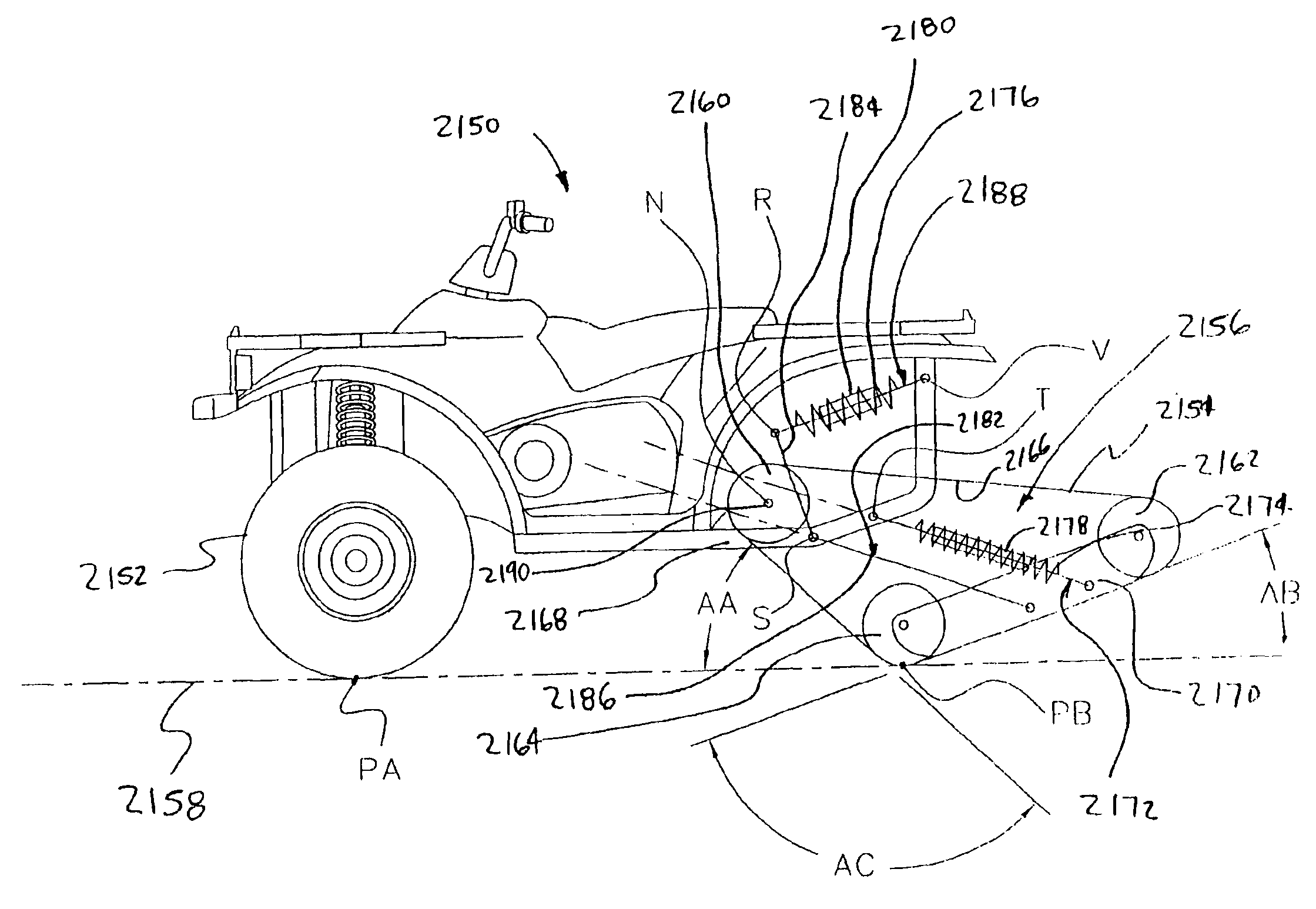
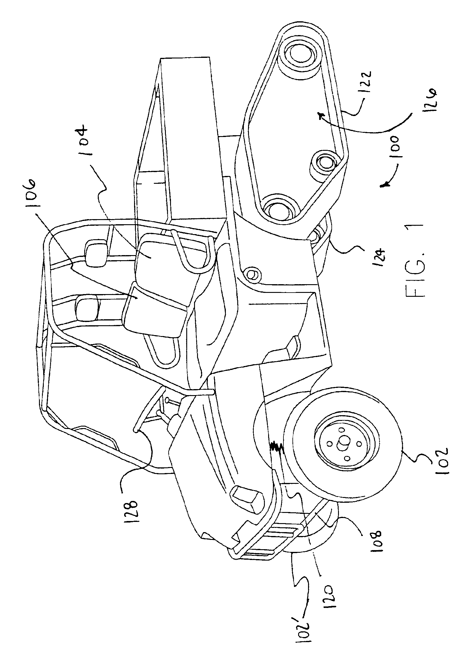
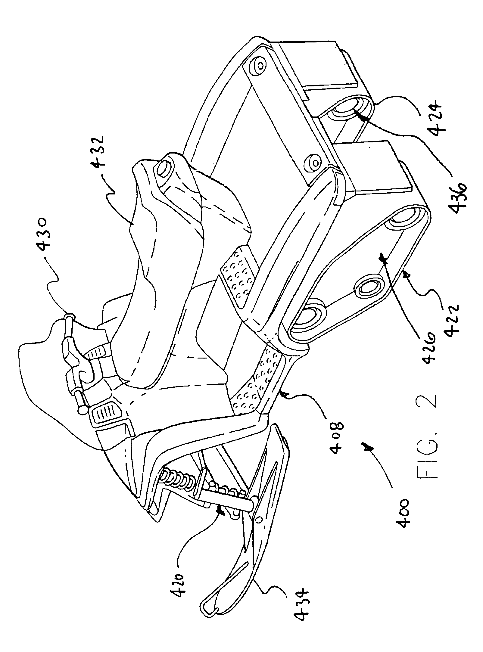
[0006]The present invention relates generally to recreational vehicles. More particularly, the present invention relates to methods and apparatus for traversing challenging terrain with a recreational vehicle. A vehicle in accordance with an exemplary embodiment of the present invention comprises a first drive track that is supported by a first rear suspension and a second drive track of vehicle is supported by a second rear suspension. The first drive track and the second drive track may be operatively coupled to an engine by a drive train for propelling the vehicle. In certain applications, the drive tracks provide a high degree of traction. The drive tracks may also be arranged to proved a relatively larger foot print which reduces the ground contract pressure of the vehicle.
[0007]In certain exemplary embodiments, the first drive track includes a plurality of first bars and the second drive track includes a plurality of second bars. The first bars of the first drive track having a first shape and the second bars of the second drive track having a second shape. In certain advantageous embodiments, the second shape is substantially a mirror image of the first shape. In some advantageous implementations, each bar has a generally arcuate shape with a concave side of each first bar facing a forward direction of the vehicle. The radius of the bars may be selected for facilitating turning of the vehicle by allowing for lateral slippage of the first drive track and the second drive track thereby reducing potential damage to turf and / or terrian under the first drive track and the second drive track.
[0009]In some useful implementations, the vehicle includes a first actuator for varying the characteristics of the first rear suspension (e.g., the spring rate) and a second actuator for varying the characteristics of the second rear suspension. In one exemplary embodiment, the first actuator comprises a first motor and the second actuator comprises a second motor. In this exemplary embodiment, the first motor and the second motor are both electrically coupled to a controller. A first encoder and a second encoder are also electrically coupled to the controller. In certain advantageous embodiments of the present invention, the controller is adapted to coordinate the motion of the left actuator and the right actuator. In these advantageous embodiments, the controller provides an easy way to adjust the suspension characteristics of the vehicle. For example, when hauling heavy loads, it may be desirable to stiffen the rear suspension. Also in these advantageous embodiments, the controller assures that the stiffness of the first rear suspension will match the stiffness of the second rear suspension.

Problems solved by technology

Modern recreational vehicles, can cover ground very rapidly and can cover great distances.
If the rider is subjected to excessive jarring while traveling over rough terrain, operator fatigue may result particularly during a long ride.

Method used


Image

  • Suspension for a tracked vehicle
  • Suspension for a tracked vehicle
  • Suspension for a tracked vehicle

Examples


Embodiment Construction

[0034]The following detailed description should be read with reference to the drawings, in which like elements in different drawings are numbered identically. The drawings, which are not necessarily to scale, depict selected embodiments and are not intended to limit the scope of the invention. Examples of constructions, materials, dimensions, and manufacturing processes are provided for selected elements. All other elements employ that which is known to those of skill in the field of the invention. Those skilled in the art will recognize that many of the examples provided have suitable alternatives that can be utilized.

[0035]FIG. 1 is an isometric view of a vehicle 100 having a first seat 104 and a second seat 106. In the embodiment of FIG. 1, first seat 104 and second seat 106 are positioned and dimensioned so as to accommodate two persons sitting in side-by-side fashion. Vehicle 100 of FIG. 1 includes a front wheel 102 that is connected to a chassis 108 of vehicle 100 by a front s...


PUM


Abstract

The present invention relates generally to recreational vehicles. More particularly, the present invention relates to methods and apparatus for traversing challenging terrain with a recreational vehicle. A vehicle in accordance with an exemplary embodiment of the present invention comprises a first drive track that is supported by a first rear suspension and a second drive track of vehicle is supported by a second rear suspension. The first drive track and the second drive track may be operatively coupled to an engine by a drive train for propelling the vehicle.

Description

RELATED APPLICATIONS[0001]This application is related to and claims priority to U.S. provisional application Ser. No. 60 / 386,025, filed Jun. 4, 2002, and entitled, “Tracked Vehicle.” The present application is also related to a U.S. patent application entitled “Tracked Vehicle” by the same inventor and filed on an even date herewith. The entire disclosure of the above-mentioned patent applications is hereby incorporated by reference.FIELD OF THE INVENTION[0002]The present invention relates generally to recreational vehicles. More particularly, the present invention relates to recreational vehicle suspensions.BACKGROUND OF THE INVENTION[0003]In recent years, recreational vehicles have gained widespread popularity. Recreational vehicles are commonly used in hunting, trail riding and utility applications such as the wide variety of maintenance activities which take place on a farm. Attachments are available which allow recreational vehicles to be used for plowing snow, mowing grass, ha...

Claims


Application Information

Patent Timeline
Patent Type & Authority Patents(United States)
IPC IPC(8): B62D55/104
CPCB62D55/02B62M27/02B62D55/108B62M2027/026
Inventor BERG, NORMAN O.
Owner POLARIS IND INC
Learn More