
Self-contained vacuum module for stencil wiper assembly

a vacuum module and stencil wiper technology, applied in the direction of cleaning with tools, printing, chemistry apparatus and processes, etc., can solve the problems of vacuum (negative), affecting the alignment procedure of circuit boards with stencils, and jeopardizing the reliability of printing processes

Active Publication Date: 2006-05-09
KPS SPECIAL SITUATIONS FUND II LP
View PDF11 Cites 45 Cited by
  • Summary
  • Abstract
  • Description
  • Claims
  • Application Information

AI Technical Summary

Benefits of technology

This configuration simplifies the cleaning process, reduces space and cost requirements, and enhances reliability by eliminating the need for extensive hose management, while maintaining effective vacuum generation for removing excess solder paste.

Problems solved by technology

This presents various problems such as the solder paste being inadvertently disposed on the unintended areas of the circuit boards thereby jeopardizing the reliability of the printing process.
Also, as the solder paste hardens, it complicates the alignment procedure of a circuit board with the stencil.
A disadvantage to the system described in Doyle, as well as other prior art wiper systems, is that a pump mechanism for creating the vacuum (negative pressure) at the vacuum plenum is typically located separate from the stencil wiper system itself.
Locating the vacuum generator remote from the wiper system has several disadvantages, such as the need to run many hoses through the machinery in order to connect the vacuum generator to the wiper system, which may be clumsy and may increase possibilities of failure of the system.
This results in a large amount of space being needed to run the several hoses to the vacuum plenum assembly and increased costs associated with the hoses and the protective casings.

Method used


Image

  • Self-contained vacuum module for stencil wiper assembly
  • Self-contained vacuum module for stencil wiper assembly
  • Self-contained vacuum module for stencil wiper assembly

Examples


Embodiment Construction

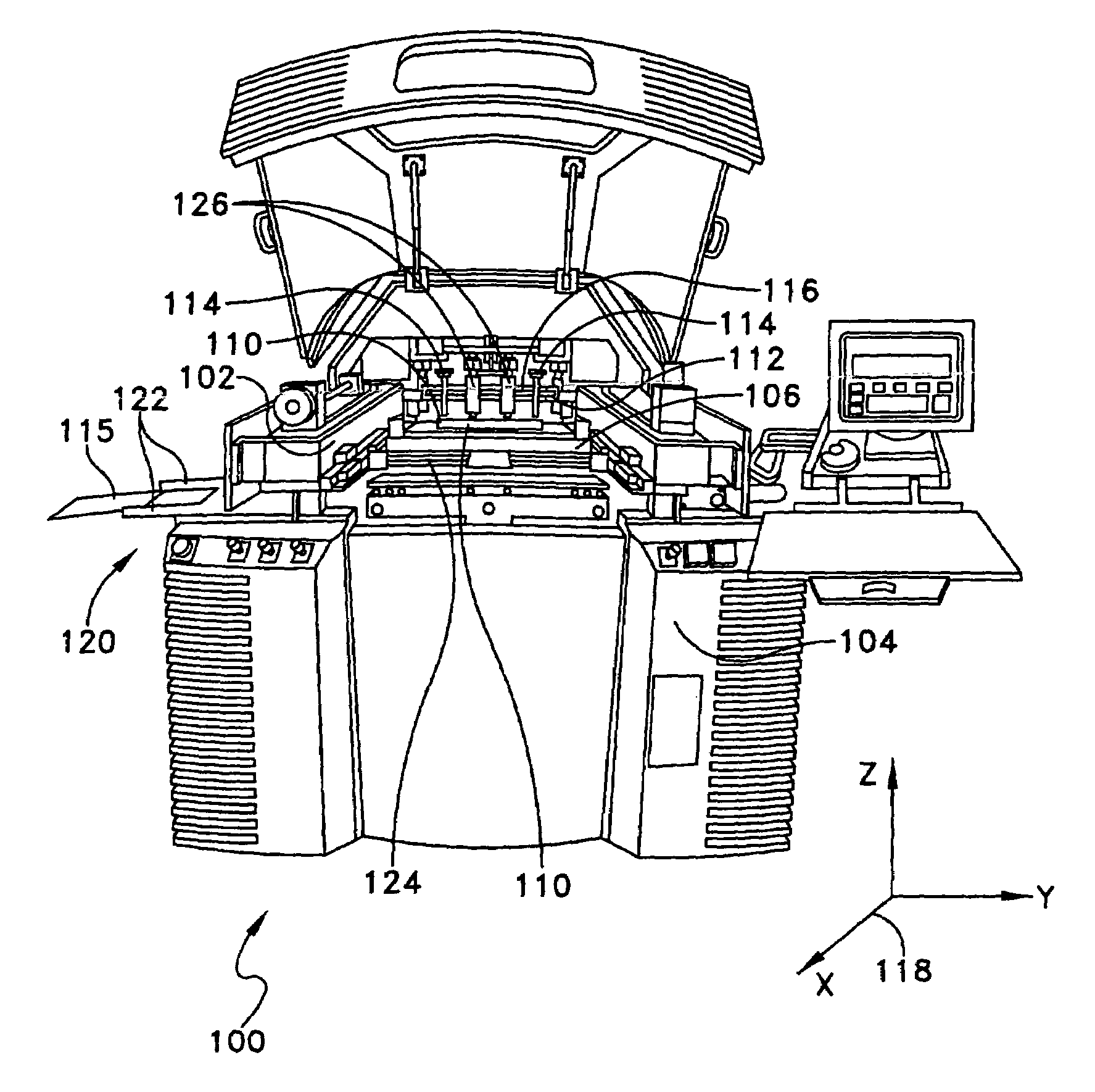
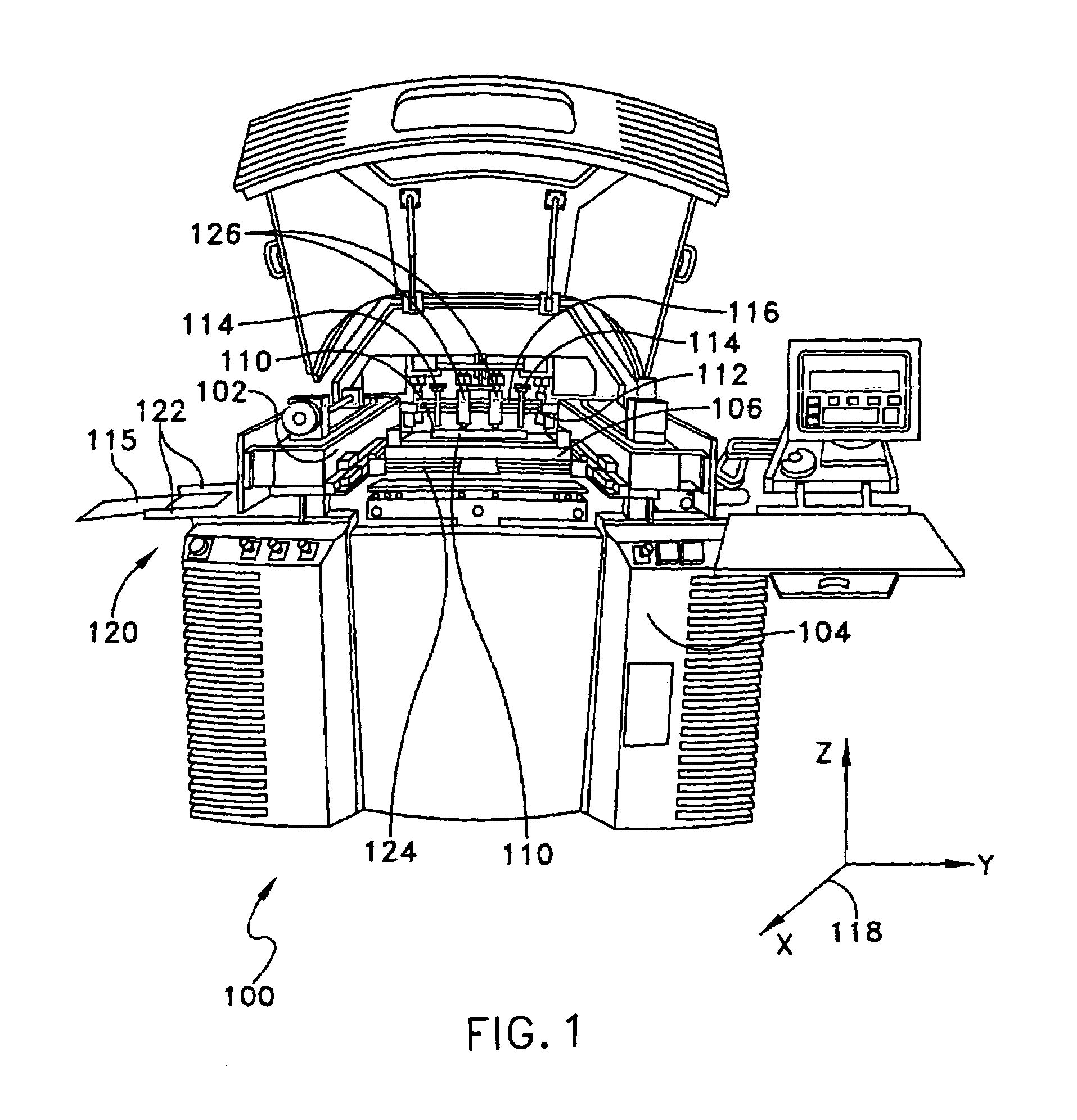
[0020]For purposes of illustration, embodiments of the present invention will now be described with reference to a stencil printer used to print solder paste onto a circuit board. One skilled in the art will appreciate, however, that embodiments of the present invention are not limited to stencil printers that print solder paste onto circuit boards, but rather, may be used in other applications requiring dispensing of other viscous materials, such as glues and encapsulents. Further, stencil printers in accordance with embodiments of the present invention are not limited to those that print solder paste on circuit boards, but rather, include those used for printing other materials on a variety of substrates. Also, the terms screen and stencil may be used interchangeably herein to describe a device in a printer that defines a pattern to be printed onto a substrate. Thus, this invention is not limited in its application to the details of construction and the arrangement of components s...


PUM


Abstract

A vacuum plenum module of a stencil wiper assembly for wiping and removing excess material from a stencil of a stencil printer includes a wiper blade to wipe the stencil, a plenum chamber in fluid communication with the wiper blade, and a vacuum generator attached to and in fluid communication with the plenum chamber to create a vacuum within the plenum chamber. The vacuum plenum module further includes a fluid supply to introduce pressurized fluid into the vacuum generator, and an exhaust to exhaust fluid from the vacuum generator. The vacuum generator includes at least one vacuum ejector adapted to create the vacuum. The vacuum plenum module is further configured to move between a first position in which the vacuum plenum is spaced away from the stencil and a second position in which the vacuum plenum engages the stencil. A method of cleaning a stencil is further disclosed.

Description

RELATED APPLICATION[0001]This application relates to U.S. patent application Ser. No. 10 / 784,122 entitled METHODS AND APPARATUS FOR CHANGING WEB MATERIAL IN A STENCIL PRINTER by Joseph Perault, Randy Peckham, Gary Freeman and Frank Marszalkowski, filed on even date herewith, and U.S. patent application Ser. No. 10 / 784,123 entitled METHODS AND APPARATUS FOR CLEANING A STENCIL by Joseph Perault and William Claiborne, filed on even date herewith. Both of these related applications are incorporated herein by reference.BACKGROUND OF INVENTION[0002]1. Field of Invention[0003]The present invention relates generally to stencil cleaning methods and apparatus, and more particularly to a stencil printer including a stencil wiper assembly having a self-contained vacuum module.[0004]2. Discussion of Related Art[0005]In a typical surface-mount circuit board manufacturing operation, a stencil printer is used to print solder paste onto a circuit board having a pattern of pads or some other conducti...

Claims


Application Information

Patent Timeline
Patent Type & Authority Patents(United States)
IPC IPC(8): B41F35/00B41L41/00
CPCB41F35/005B41P2235/27B41P2235/24B41F15/06B41F35/003H05K3/1216
Inventor PERAULT, JOSEPH A.CLAIBORNE, WILLIAM RUSSELL
Owner KPS SPECIAL SITUATIONS FUND II LP
Learn More