Eureka AIR delivers breakthrough ideas for toughest innovation challenges, trusted by R&D personnel around the world.

Interlocking erosion control block with diagonal cable channels

a technology of erosion control and cable channels, which is applied in the direction of coastline protection, marine site engineering, construction, etc., can solve the problems of compromising the structural integrity of the mat, affecting the stability of the mat, and wasting time and money to replace or repair damaged blocks, etc., to achieve the effect of resisting torsional movemen

Inactive Publication Date: 2006-05-02
EROSION PREVENTION PRODS
View PDF21 Cites 39 Cited by
  • Summary
  • Abstract
  • Description
  • Claims
  • Application Information

AI Technical Summary

Benefits of technology

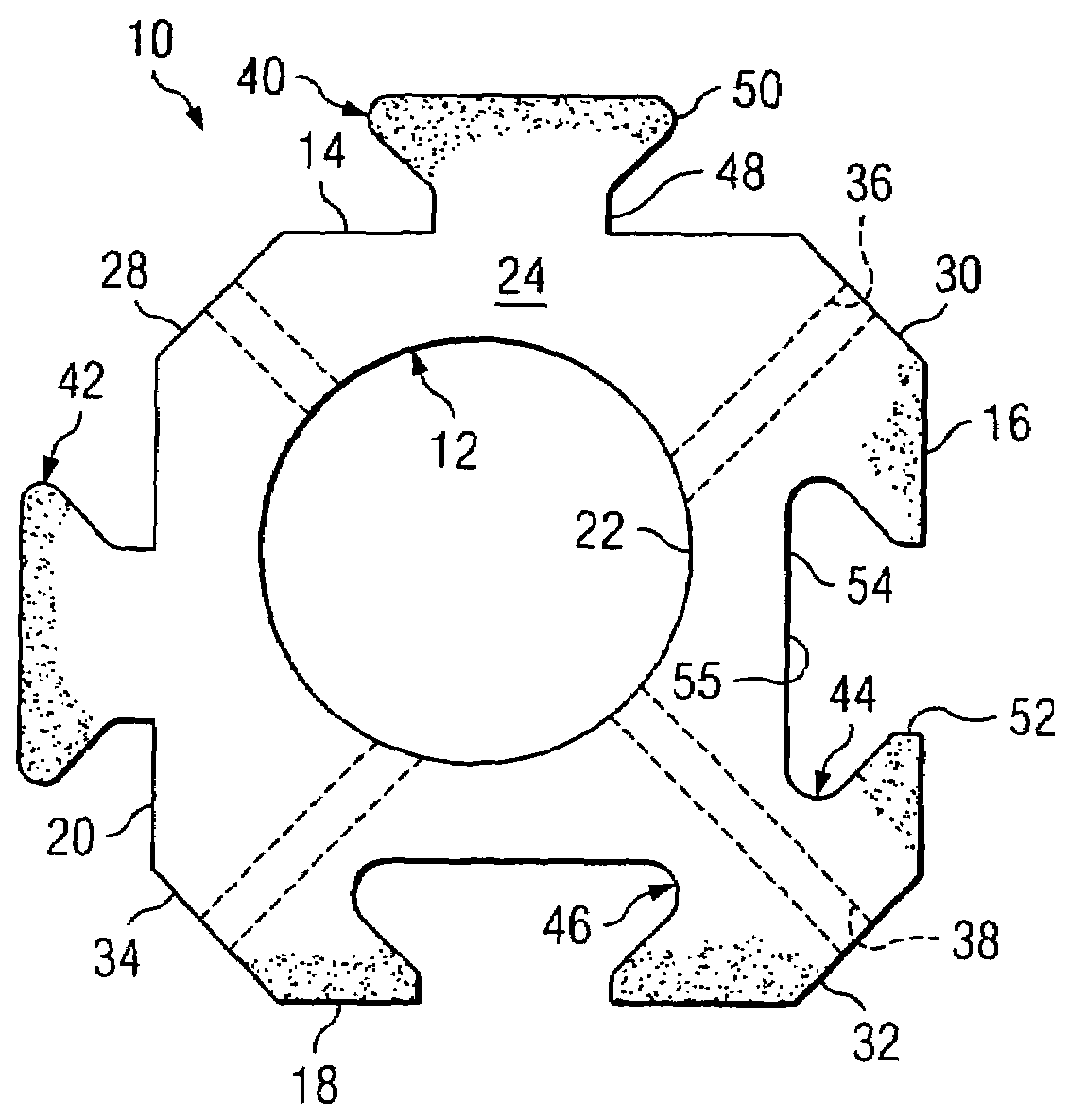
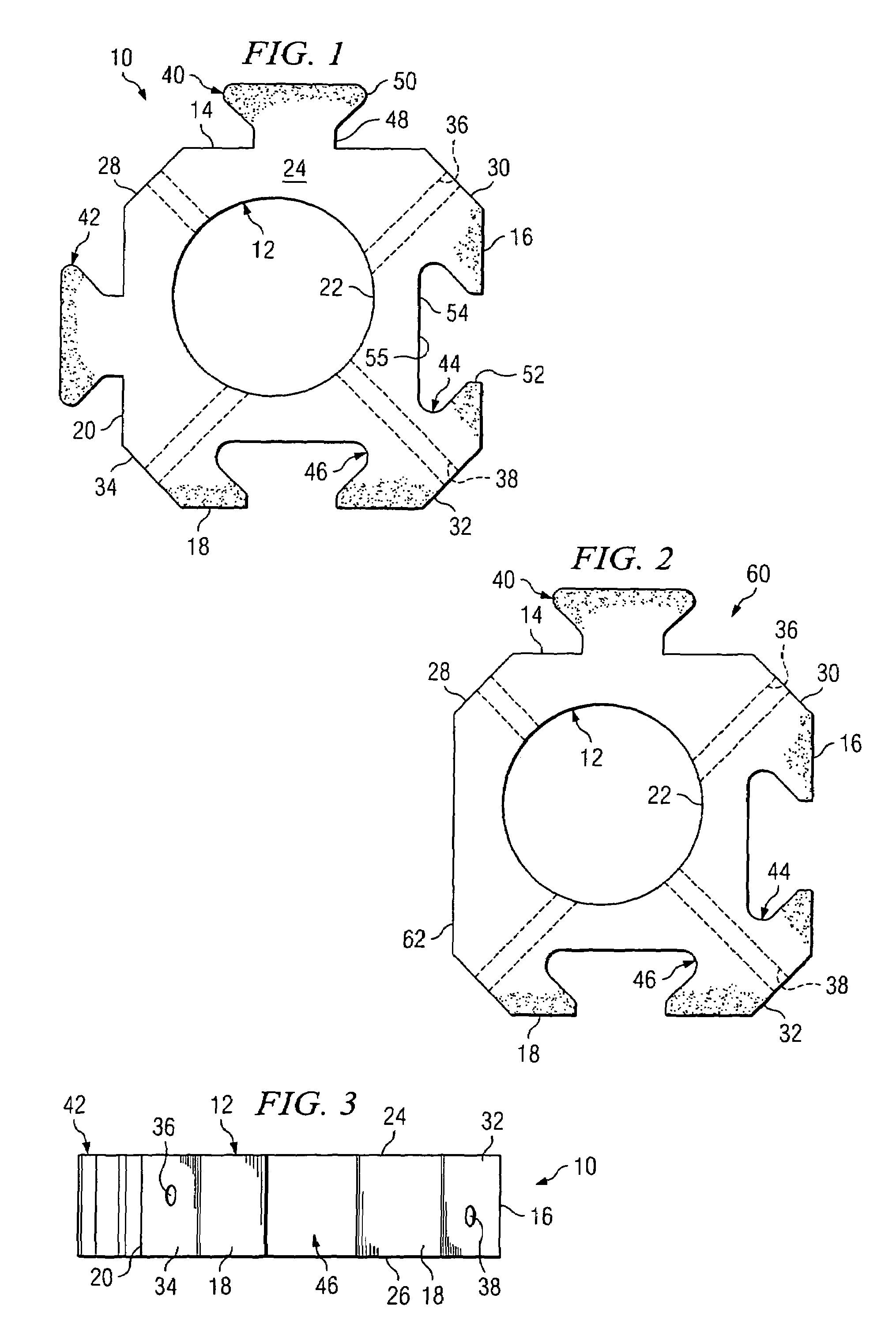
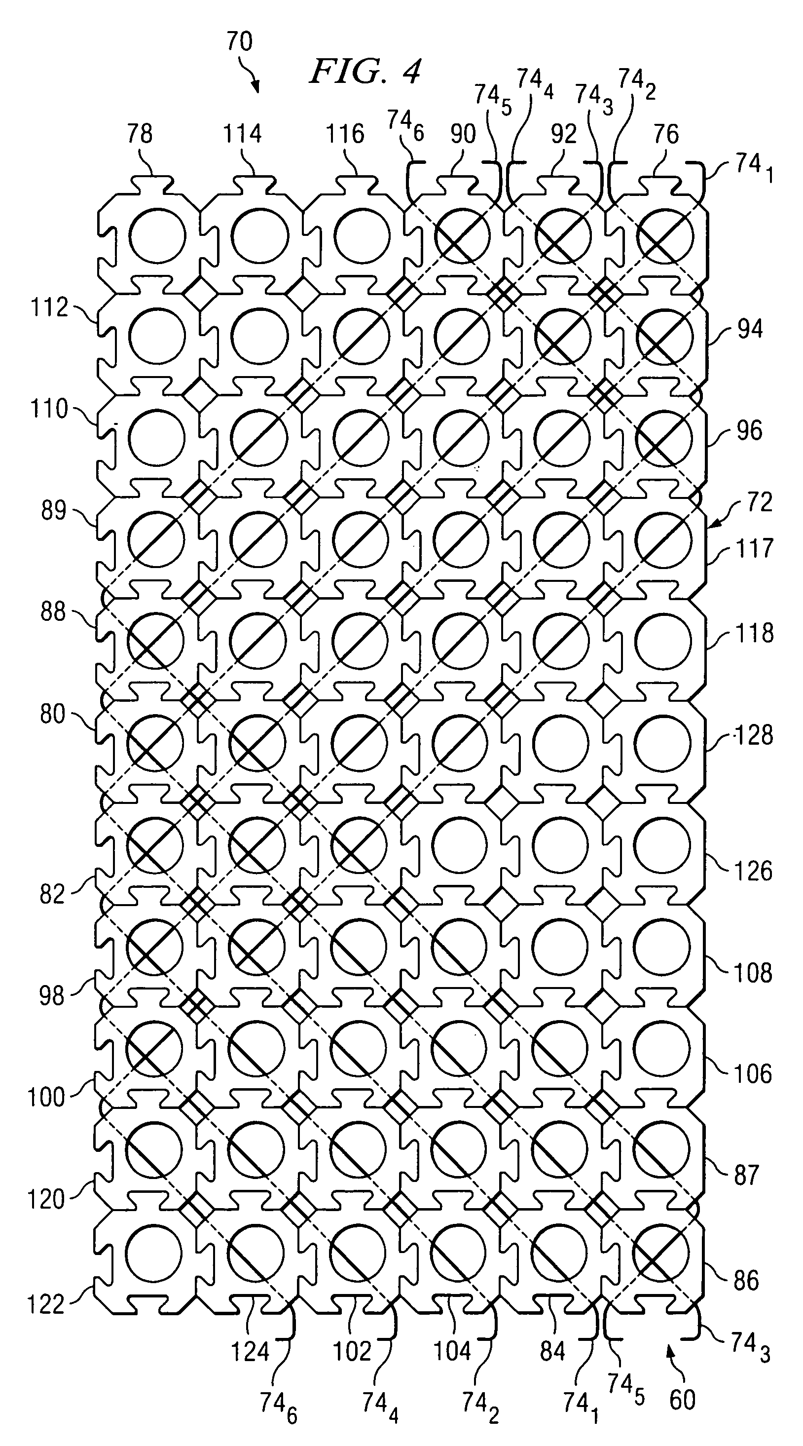
[0009]In accordance with one embodiment of the invention, disclosed is a generally rectangular-shaped erosion control block adapted for cabling to other similar blocks, where the blocks have diagonal cable channels formed therethrough. With this arrangement of cable channels, the cables threaded through the cable channels exit the blocks at the respective corners thereof. The blocks of the mat are thus individually more stable and resistant to torsional movement.

Problems solved by technology

If the blocks are subjected to torsional forces while being interlocked, such as when lifted in a mat, then the arms and / or sockets of the individual blocks can be damaged or broken.
Damaged or broken blocks of a mat compromise the structural integrity of the mat.
Moreover, it is time consuming and expensive to uncable a mat and replace or repair damaged blocks.
This represents a rather unstable situation for the blocks, as they tend to rotate a small amount about the cables.

Method used


Image

  • Interlocking erosion control block with diagonal cable channels
  • Interlocking erosion control block with diagonal cable channels
  • Interlocking erosion control block with diagonal cable channels

Examples


Embodiment Construction

[0024]With reference to FIGS. 1 and 3, there is shown respective top and side views of an erosion control block 10 constructed according to one embodiment of the invention. The block 10 includes a body 12 formed with a heavy material, such as concrete. Preferably, although not by necessity, the block 10 can be made by block plant techniques. In forming the erosion control block 10, the body 12 is formed with four sides, including a north side 14, an east side 16, a south side 18 and a west side 20. The north, east, etc., designations are merely to identify and describe the different attributes of the block 12, and do not reflect any actual directional or positioning requirements. In terms of size, the block 10 is about fifteen inches between the sides 16 and 20, and about fifteen inches between the sides 14 and 18. A block thickness of about 4.5 inches provides a weight of about sixty pounds. In order to achieve a heavier block, it can be made thicker. Formed in the body 12 of the b...


PUM


Abstract

An erosion control block having male tab members and female socket members providing an interlocking relationship with neighbor blocks so that lateral removal therebetween is prevented. The erosion control block includes cable channels formed therein from respective opposite corners of the block so that an axis of the cable channels forms an “X” in said block.

Description

RELATED APPLICATION[0001]This patent application is a divisional of patent application entitled “Method of Forming A Mat of Erosion Control Blocks.” filed Feb. 17, 2004, and accorded Ser. No. 10 / 780,433, now U.S. Pat. No. 6,955,500. The subject matter of the pending application is incorporated herein be reference.TECHNICAL FIELD OF THE INVENTION[0002]The present invention relates in general to erosion control blocks, and more particularly to an interlocking erosion control block with cable channels formed therein.BACKGROUND OF THE INVENTION[0003]The erosion of soil, sand and other earth material has been controlled for many years by the use of erosion control blocks. The prior art is replete with erosion control blocks of all types, shapes and sizes. The primary function of erosion control blocks is to partially cover the ground to be protected and slow the flow of water thereover. A porous geotextile fabric is first laid on the ground. Depending on the area of the ground to be prot...

Claims


Application Information

Patent Timeline
Patent Type & Authority Patents(United States)
IPC IPC(8): E02B3/14
CPCE02B3/14
Inventor SMITH, LEE A.SMITH, BELINDA F.
Owner EROSION PREVENTION PRODS
Why Eureka
Eureka Blog
Learn More