
Device and method for mounting parts

a technology for mounting parts and components, applied in metal-working equipment, metal-working equipment, manufacturing tools, etc., can solve the problems of degrading the quality of mounting, and deteriorating the fixing surface of the component-mounted board

Inactive Publication Date: 2006-05-02
PANASONIC CORP
View PDF22 Cites 32 Cited by
  • Summary
  • Abstract
  • Description
  • Claims
  • Application Information

AI Technical Summary

Benefits of technology

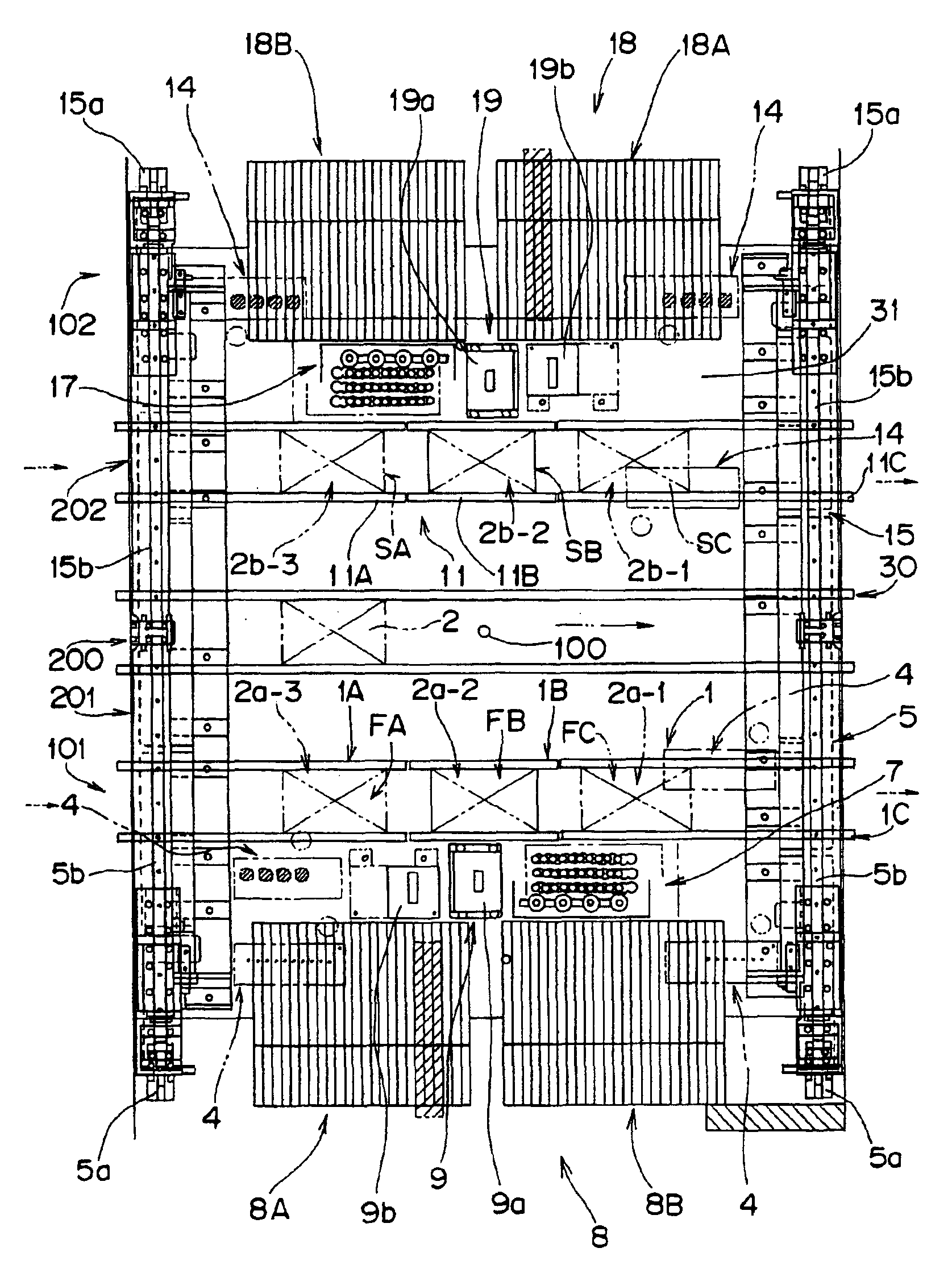
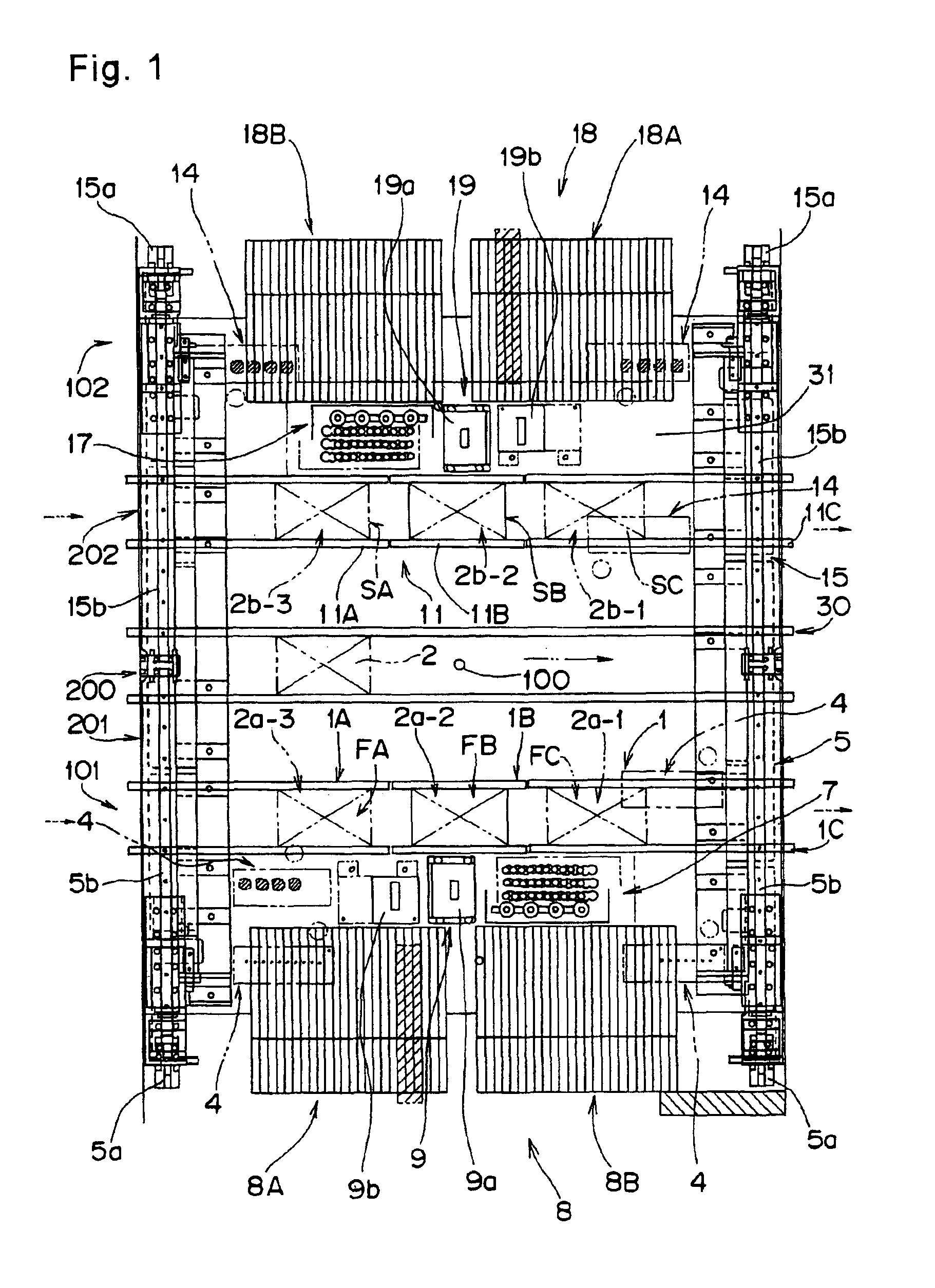
"The present invention provides a component mounting apparatus with two mounting units that can hold and position components on circuit boards. The first mounting unit can hold and position components on a first circuit board in a first area, while the second mounting unit can hold and position components on a second circuit board in a second area. The first mounting unit can also hold and position components on a first board in a first pre-placement standby position, a first placement position, and a first post-placement standby position. The second mounting unit can hold and position components on a second board in a second pre-placement standby position, a second placement position, and a second post-placement standby position. The apparatus can also have separate control for each mounting unit, allowing for independent operation. Additionally, the apparatus can have a two-dimensional camera for improved recognition of components."

Problems solved by technology

Therefore, if unloading of a component-mounted board, i.e. a completed product of which the component mounting has ended, is stopped for a long term, solder of the component-mounted board would be deteriorated, which may lead to a degraded mounting quality.
Moreover, when mounting process time for performing component mounting of boards of different models differs between the front-side component mounting work area and the rear-side component mounting work area, or when the mounting process time differs due to a suction error or a recognition error during component mounting in, for example, the rear-side component mounting work area even in a case of mounting of identical boards and components.
If a component-mounted board of which a component mounting has previously ended is made to stand by for a long period, then solder of the component-mounted board would be deteriorated, which may lead to a degraded mounting quality, as in the above case.

Method used


Image

  • Device and method for mounting parts
  • Device and method for mounting parts
  • Device and method for mounting parts

Examples


first embodiment

(First Embodiment)

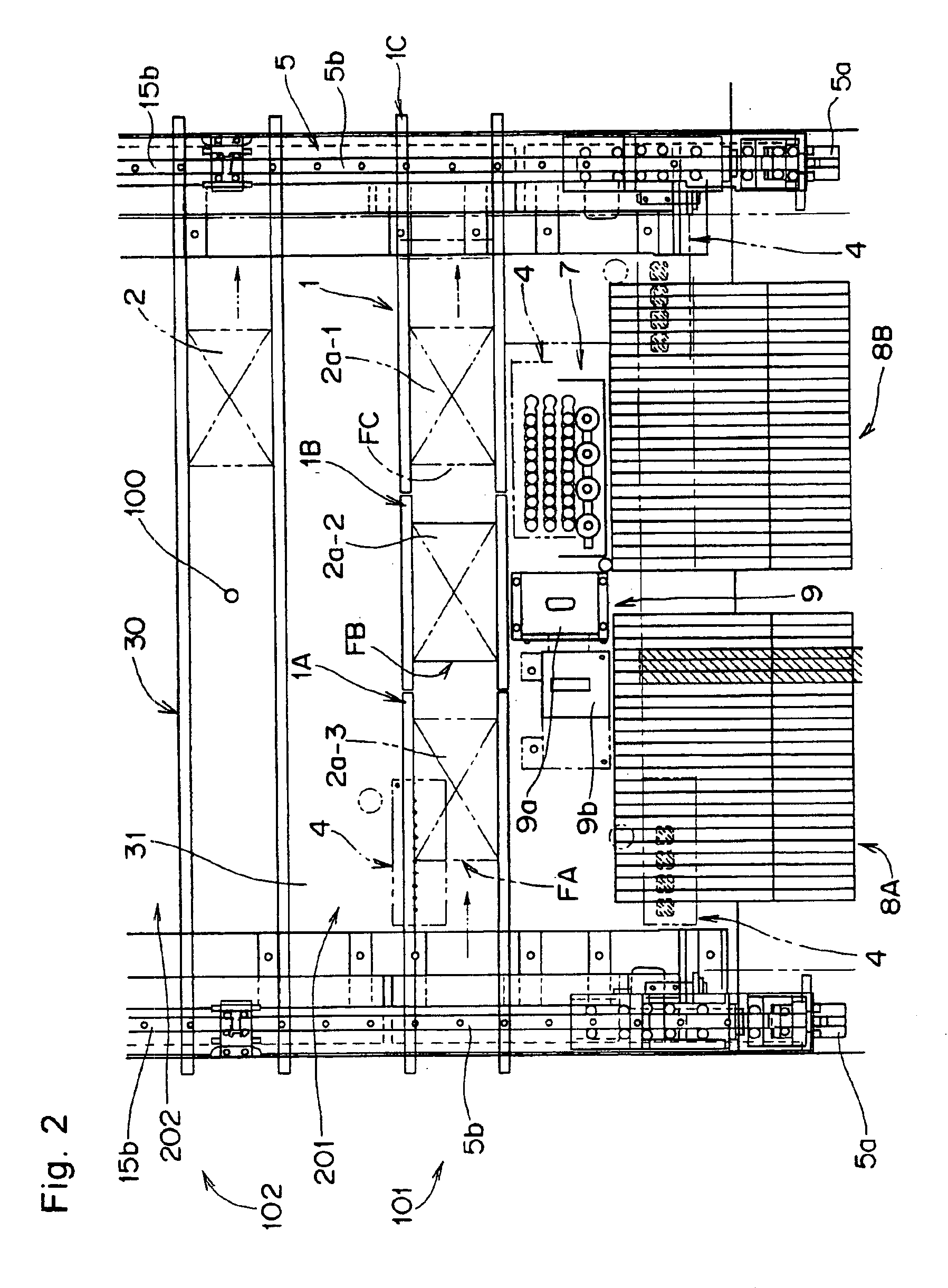
[0138]As shown in FIGS. 1 through 3, a component mounting apparatus capable of performing a component mounting method according to a first embodiment of the present invention can mount components on a board 2, which is one example of a circuit formation article and on which components are to be mounted, with remarkably improved productivity per device installation area. It is noted here that the term “components” includes electronic components, mechanical components, optical components and the like. The term “circuit formation article” refers to objects on which a circuit is formed, exemplified by such circuit boards as resin boards, paper-phenol boards, ceramic boards, glass epoxy boards and film boards, such circuit boards as single-layer boards or multilayer boards, and components, casings, frames or the like.

[0139]In a component mounting work area of one component mounting apparatus described above, two electronic circuit boards 2 (first board 2a and second boa...

second embodiment

(Second Embodiment)

[0214]A component mounting system and method of a second embodiment of the present invention will be described next with reference to FIG. 10 through FIG. 22.

[0215]According to this second embodiment, as shown in FIG. 10, a plurality of component mounting apparatuses according to the first embodiment are joined together to constitute an electronic component-mounted board production line, and a board (unmounted board or bare board) 2c to be mounted with components is efficiently loaded into each component mounting apparatus, and a mounted board 2d is unloaded. It is to be noted that this second embodiment is provided for handling a board that is unloaded from a printer and mounted with no electronic component However, the present invention is not limited to this and is allowed to be applied even in, for example, a case where an electronic component(s) is to be further mounted on a board on which electronic components have already been partially mounted in the cours...


PUM

PropertyMeasurementUnit
phase angleaaaaaaaaaa
angleaaaaaaaaaa
angleaaaaaaaaaa

Abstract

A first mounting unit and a second mounting unit capable of performing component holding, component recognition, and component placement for two boards independently of each other are provided. A first conveyance path for loading and unloading the first board, and a second conveyance path for loading and unloading the second board, are independently arranged.

Description

[0001]This application is a National Stage application of PCT / JP01 / 07138, filed Aug. 21, 2001.TECHNICAL FIELD[0002]The present invention relates to a component mounting apparatus and method for placing components fed from a component feeding device onto a board or other circuit formation article, and also relates to a component mounting system equipped with a plurality of such component mounting apparatuses.BACKGROUND ART[0003]Conventionally, as shown in FIG. 9, the present applicant has already proposed a component mounting apparatus in which its component mounting work area 2200 is divided into a front-side component mounting work area 2201 and a rear-side component mounting work area 2202 viewed from an operator. Each of the areas is provided with component feeding devices 2008A, 2008B, 2018A and 2018B and component recognition devices 2009 and 2019, and a front-side board conveying and holding device 2003 and a rear-side board conveying and holding device 2013 which can be later...

Claims


Application Information

Patent Timeline
Patent Type & Authority Patents(United States)
IPC IPC(8): B23P19/00H05K13/00H05K13/04
CPCH05K13/0061H05K13/04Y10T29/53178Y10T29/53191Y10T29/53396H05K13/085H05K13/00
Inventor KABESHITA, AKIRAMIMURA, NAOTOYOSHIDA, NORIAKIMISAWA, YOSHIHIKOKAWASE, TAKEYUKIHACHIMURA, TETSUTAROUNISHIWAKI, TOSHIROISHII, TAIRAKAWATE, MITSUOWATANABE, HIDEAKI
Owner PANASONIC CORP
Learn More