
Extension of fast phong shading technique for bump mapping

a bump mapping and phong shading technology, applied in the field of computer graphics, can solve the problems of affecting the quality of 3d images produced by these methods, placing a significant burden on the processing power of the computer, and significantly slowing the image generation process of rendering,

Inactive Publication Date: 2006-04-25
INTEL CORP
View PDF5 Cites 1 Cited by
  • Summary
  • Abstract
  • Description
  • Claims
  • Application Information

AI Technical Summary

Benefits of technology

[0011]The present invention provides per-pixel shading that is fast enough for real time interactive graphics applications and may be implemented using standard graphics hardware.

Problems solved by technology

This places a significant burden on the processing power of the computer.
Since there are tens to hundreds of pixels per polygon, rendering significantly slows the image generation process.
The images produced by these methods lack the lighting effects that distinguish quality 3D images, such as realistic specular highlights and diffuse light scattering.
In addition, these methods are not amenable to bump mapping, since per pixel normal orientations are never determined.
Even with high quality graphics hardware, the computational cost of Phong shading makes it difficult to generate real-time, interactive 3D images.

Method used


Image

  • Extension of fast phong shading technique for bump mapping
  • Extension of fast phong shading technique for bump mapping
  • Extension of fast phong shading technique for bump mapping

Examples


Embodiment Construction

[0024]The following discussion sets forth numerous specific details to provide a thorough understanding of the invention. However, those of ordinary skill in the art, having the benefit of this disclosure, will appreciate that the invention may be practiced without these specific details. In addition, various well known methods, procedures, and components have not been described in detail in order to focus attention on the features of the present invention.

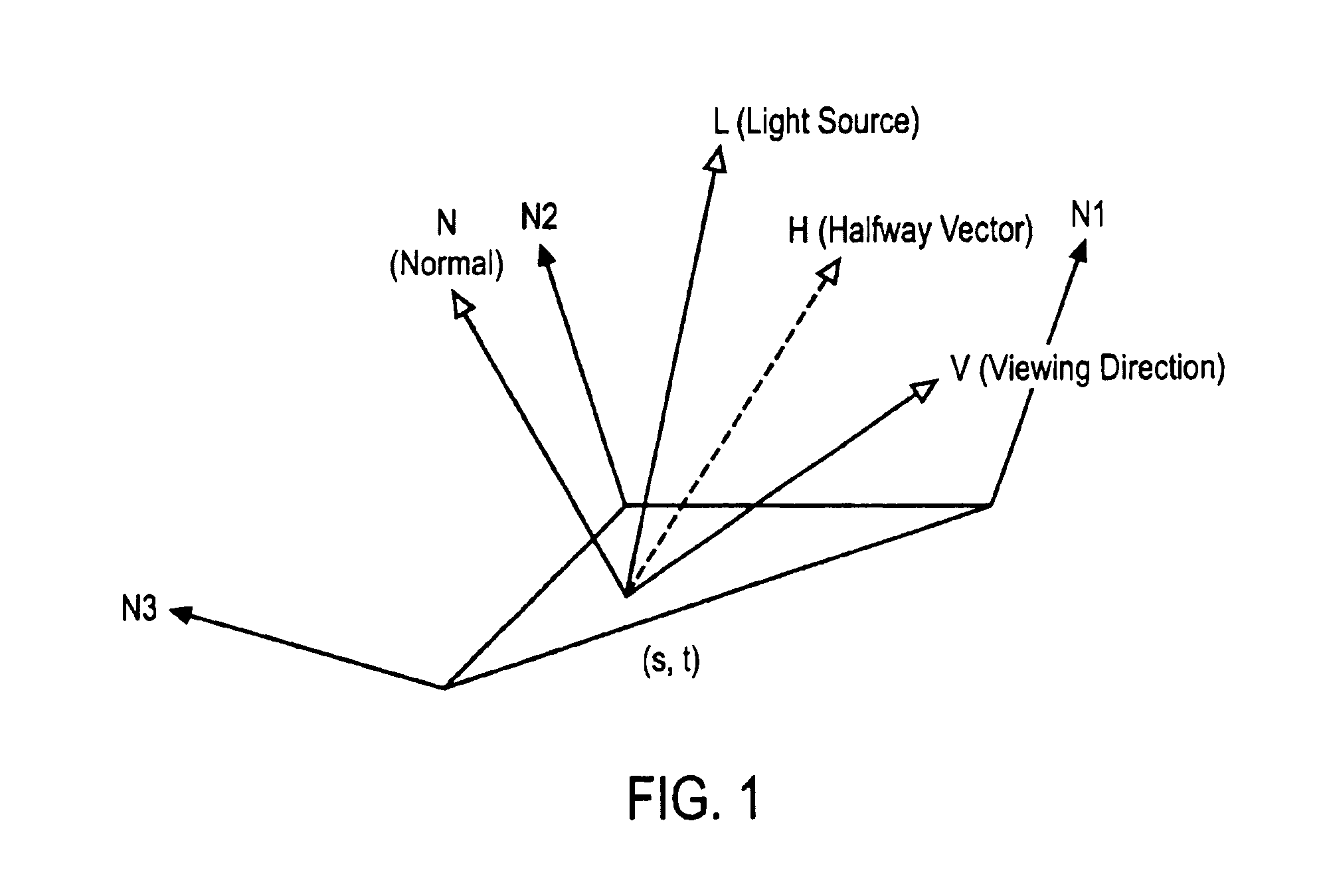
[0025]FIG. 1 shows the different vectors that are associated with a polygon P for implementing various illumination models. In the following discussion, vectors and matrices are represented by bold capital letters. P is shown as a triangle for purposes of illustration with the understanding that any type of convex, planar polygon may be used to approximate the surface of an object. Vectors N, L, V, and H are shown for an arbitrary set of surface coordinates (s, t) on P. N is a unit vector that is normal to P at (s, t). L is a unit...


PUM


Abstract

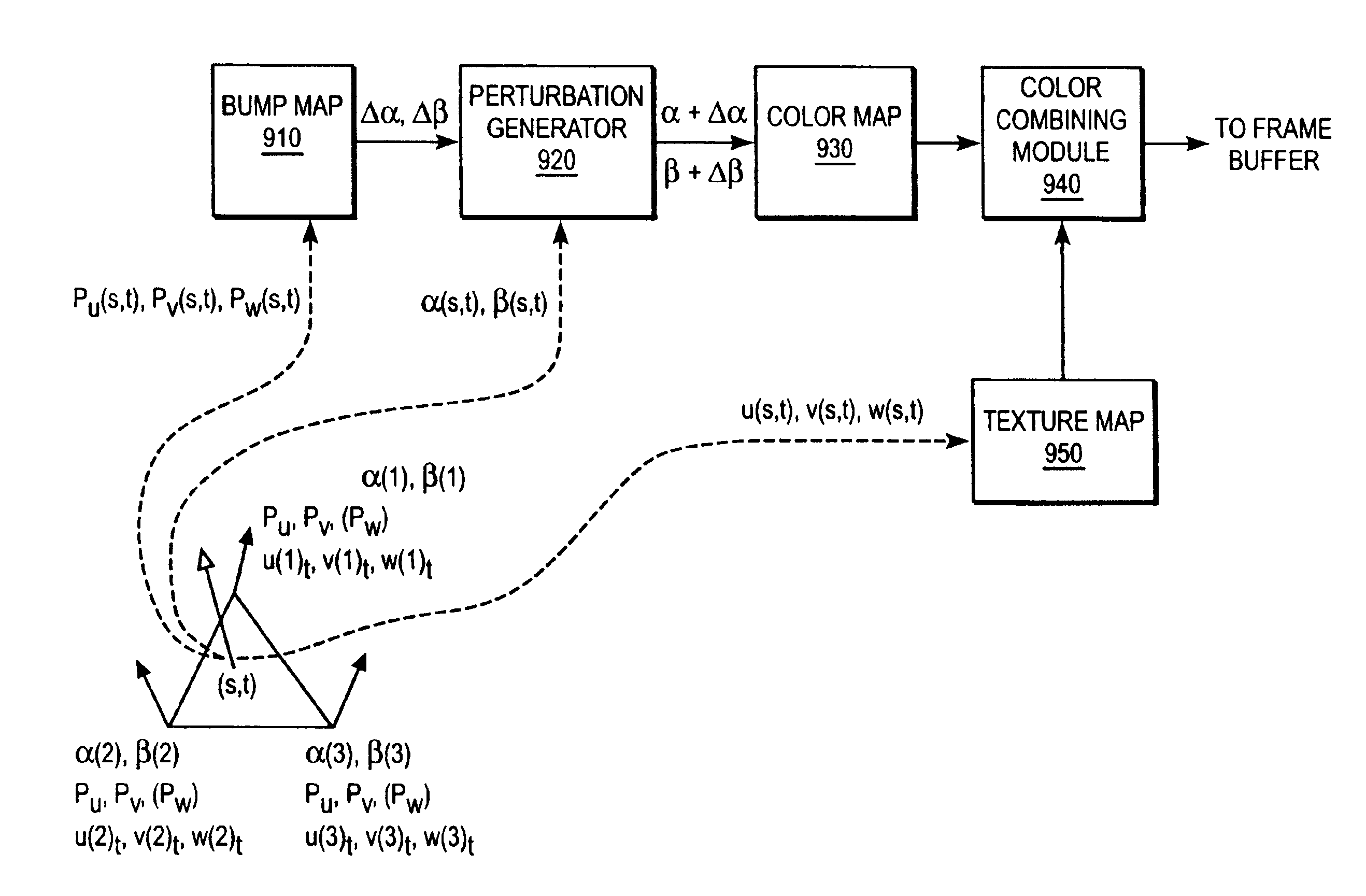
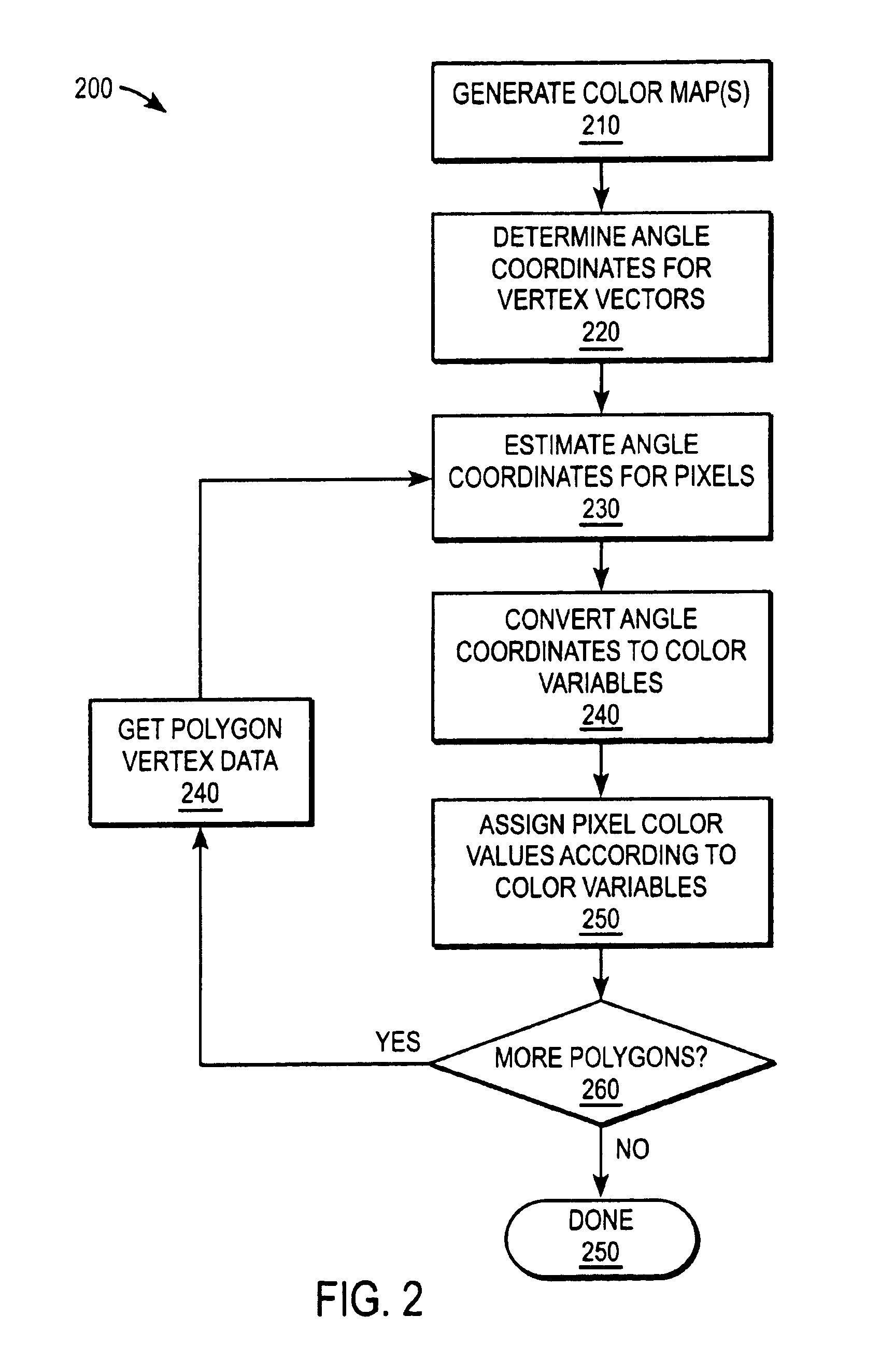
A method for implementing bump mapping is provided that is fast enough to be used with real time interactive graphics products. Computationally expensive color values are precalculated for a sample of normal vector orientations as a function of orientation-dependent color variables, collected in a color map, and referenced through the color variables. The color variables are linearly related to angle coordinates that specify the normal vector orientations in a selected coordinate system. Angle coordinates are determined for the vertices of the polygons representing the object to be imaged. During rendering, the vertex angle coordinates are interpolated to provide pixel angle coordinates. Modified angle coordinates are generated by combining the angle coordinates with angle perturbations provided by a perturbation source, and converted to color variables. Color values referenced by the color variables are assigned to the corresponding pixels.

Description

[0001]This patent application is related to U.S. patent application Ser. No. 09 / 118,581, entitled “System and Method for Fast Phong Shading”.BACKGROUND OF THE INVENTION[0002]1. Technical Field[0003]This invention relates to the field of computer graphics, and in particular to methods for implementing bump mapping in computer graphics.[0004]2. Background Art[0005]Computer images having realistic three dimensional appearances (“3D images”) are becoming increasingly prevalent in games, multi-media, and other graphics-heavy software. The methods employed to generate 3D images require processing power that has only recently become available in personal computers. A standard method for generating a 3D image begins with sets of polygons that represent the surfaces of each object in the image. An object that has a moderately complex shape may require thousands of polygons to represent its surface, and an image that includes multiple objects may require tens or even hundreds of thousands of ...

Claims


Application Information

Patent Timeline
IPC IPC(8): G06T15/50
CPCG06T15/506
Inventor HURLEY, JAMES T.PLETENEV, FEDOR A.
Owner INTEL CORP
Learn More