
Enhanced predistortion method and apparatus

a predistortion and amplifier technology, applied in the field of predistortion methods, can solve the problems of low btss capacity, inability to provide full 3g mobile services, and difficulty in implementing high-capacity btss using current bts infrastructure,

Inactive Publication Date: 2006-04-18
ALCATEL-LUCENT USA INC
View PDF7 Cites 2 Cited by
  • Summary
  • Abstract
  • Description
  • Claims
  • Application Information

AI Technical Summary

Benefits of technology

[0006]In order to compensate for the non-linearity of an amplifier, the amplifier may be operated in a linear zone. That is, the lower the power level of the amplifier, the smaller the non-linearity manifested by the amplifier. However, this may unnecessarily limit the acceptable operating range of the amplifier, since the amplifier must be operated below maximum power output to avoid undesirable non-linearity.

Problems solved by technology

Networks and base transceiver stations (BTSs) for third generation systems have been deployed; however, these BTSs do not have the capabilities needed to provide full 3G mobile services.
However, total power consumption of high-capacity BTSs that are required tends to be higher than that of current lower capacity BTSs, because the high-capacity BTSs use more radio frequency (RF) carriers and have more baseband signal processing units.
This increased power consumption makes it difficult to implement the high-capacity BTSs using current BTS infrastructure.
In particular, the heat produced by the power amplifiers implemented in high-capacity BTSs overwhelms the heat removal capacity of the current BTS infrastructure.
However, in reality, amplifiers exhibit non-ideal properties such as non-linear amplitude and phase distortion, which are undesirable and may deteriorate performance of a system employing the amplifier.
This effect is known as intermodulation distortion (IMD) and is particularly undesirable in high-power radio frequency (RF) amplifiers designed for use in multicarrier or multichannel systems.
For example, a broadband amplifier used in a wireless system may generate various undesirable intermodulation products as a result of amplifying a multitude of channels occurring at fixed frequency intervals across a band.
However, this may unnecessarily limit the acceptable operating range of the amplifier, since the amplifier must be operated below maximum power output to avoid undesirable non-linearity.
Moreover, the determined distortion parameters may not be optimum for various amplifier input signals.

Method used


Image

  • Enhanced predistortion method and apparatus
  • Enhanced predistortion method and apparatus
  • Enhanced predistortion method and apparatus

Examples


Embodiment Construction

[0018]The exemplary embodiments of the present invention described herein are merely illustrative of the present invention. Therefore, the exemplary embodiments should not be considered as limiting of the present invention.

[0019]First, a transmitter according to an embodiment of the present invention will be described. Second, a method of predistorting a signal will be described. Finally, alternative embodiments of the present invention will be described.

Transmitter Embodiment

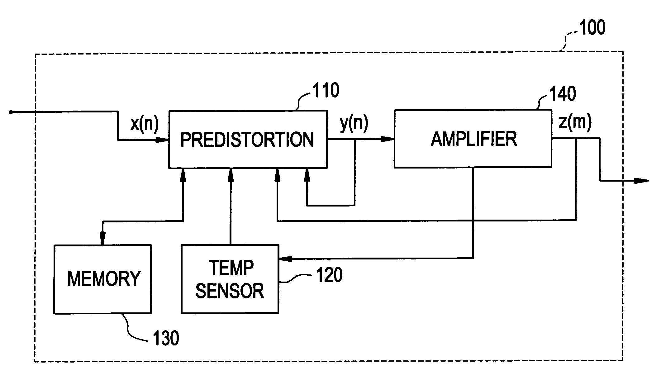
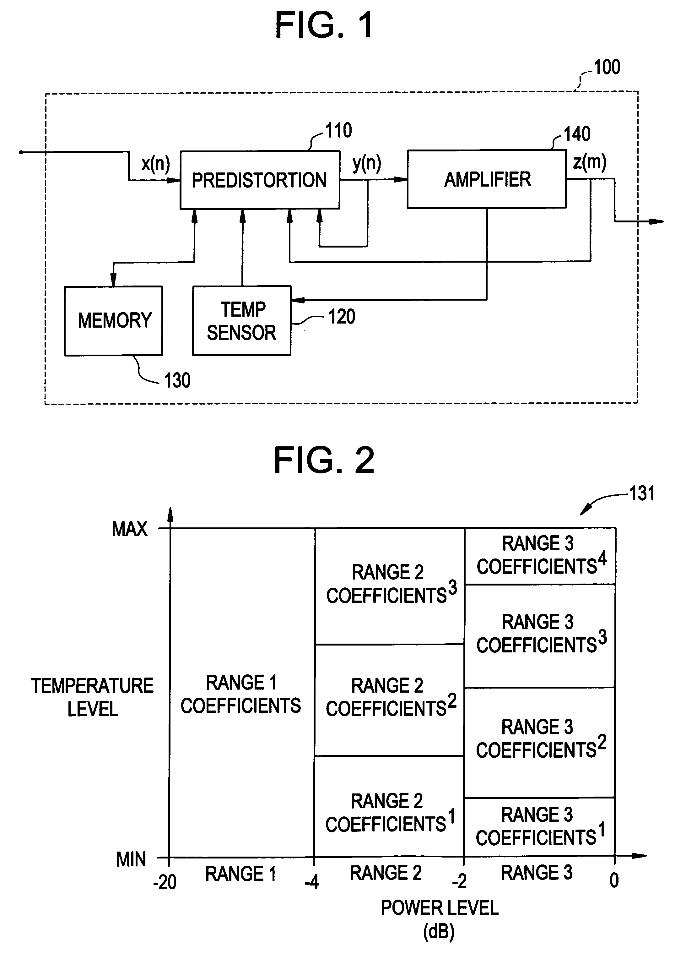
[0020]FIG. 1 illustrates a transmitter 100 implementing a predistorting method in accordance with an exemplary embodiment of the present invention. The transmitter 100 may be implemented in a various number of devices that transmit signals. For example, the transmitter 100 may be used in a base transceiver station (BTS), a transceiver, etc.

[0021]The transmitter 100 includes a predistortion block 110, a temperature sensor 120, a memory 130, and an amplifier section 140. A source signal x(n) is input to the trans...


PUM


Abstract

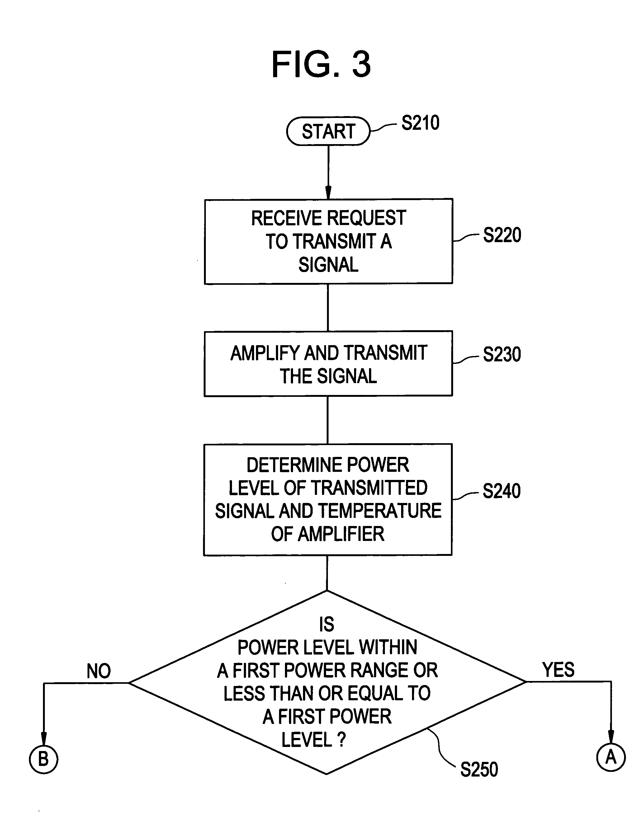
A method may include determining a power level of a signal and a temperature level of a transmitter originating the signal. At least one of the power and temperature levels may be compared to a lookup table containing predistortion coefficients. The method is capable of predistorting a signal based on the comparison. An apparatus is disclosed in relation to the method.

Description

BACKGROUND OF THE INVENTION[0001]The present invention generally relates to predistortion methods, in particular, predistortion methods used in conjunction with amplifiers.[0002]Current wideband code division multiple access (W-CDMA) third generation (3G) systems will likely form an infrastructure for mobile speech, video, and high-speed data communications. The number of broadband Internet services is rapidly increasing in fixed networks, and people accustomed to having a broadband environment in their home are now beginning to expect a similarly broadband mobile environment. As a result, the 3G systems are evolving to accommodate more subscribers and provide broadband mobile data communications.[0003]Networks and base transceiver stations (BTSs) for third generation systems have been deployed; however, these BTSs do not have the capabilities needed to provide full 3G mobile services. The next phase of equipment should support greater capacities and faster data services such as hig...

Claims


Application Information

Patent Timeline
IPC IPC(8): H03F1/26H03F1/32H03F1/30H04B1/04
CPCH03F1/3241H04B1/0475H04B2001/0425
Inventor HONCHARENKO, WALTERKIM, JAEHYEONGKONSTANTINOU, KYRIAKI
Owner ALCATEL-LUCENT USA INC
Learn More