
Electronic timepiece with a date display function

Active Publication Date: 2006-04-11
SEIKO EPSON CORP
View PDF21 Cites 69 Cited by
  • Summary
  • Abstract
  • Description
  • Claims
  • Application Information

AI Technical Summary

Benefits of technology

[0013]The present invention is therefore directed to solving these problems, and an object of this invention is to provide an electronic timepiece with a date display function whereby the user can more easily adjust the date, and whereby power consumption, when the user adjusts the date, is reduced.SUMMARY OF THE INVENTION

Problems solved by technology

A problem with this simple date display mechanism is that at the end of the month in months shorter than 31 days in the solar calendar (that is the short months of February, April, June, September, and November), a non-existent date that is not actually on the calendar is displayed.
A problem with this mechanical timepiece is that many more gears than typical are required, resulting in a complicated mechanism and high production costs.
A problem with such electronic timepieces is that the user must adjust the calendar information to the actual date if the date displayed in the date window becomes different from the actual date as a result of replacing the battery.
A problem with this electronic timepiece is that if the date displayed in the date window is offset much from the actual date, the actuator must rotationally drive the day wheel a corresponding distance to adjust the date, and this consumes much power.
If much power is consumed to adjust the date in an electronic timepiece powered by a secondary cell in particular, the resulting voltage drop could cause the electronic timepiece itself to stop.
A further problem is that it takes a while to finish adjusting the date if the actuator must rotationally drive the day wheel very far.
A yet further problem with this electronic timepiece of the prior art is that adjusting the calendar information stored in the IC is difficult and complex.
When the displayed date and the actual date are offset in a conventional electronic timepiece as described above, the user must perform an adjustment sequence such as described above, and this operation can be extremely complicated.
Furthermore, adjusting the calendar information is particularly difficult if the user forgets this adjustment procedure.

Method used


Image

  • Electronic timepiece with a date display function
  • Electronic timepiece with a date display function
  • Electronic timepiece with a date display function

Examples


Embodiment Construction

[0047]Preferred embodiments of the present invention are described below with reference to the accompanying figures. The present invention is described applied to a wristwatch by way of example. The date in each of the following embodiments is based on the solar calendar.

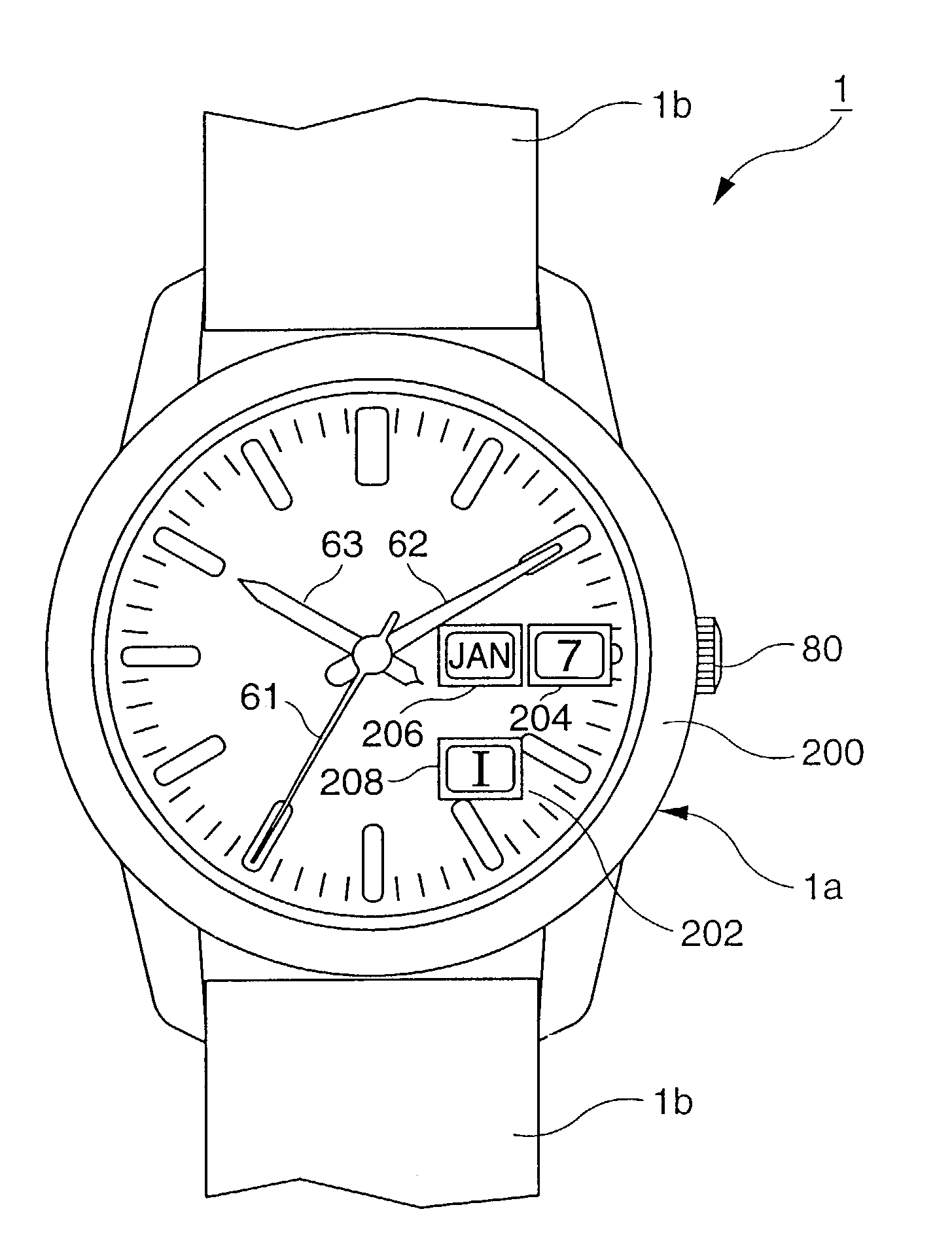
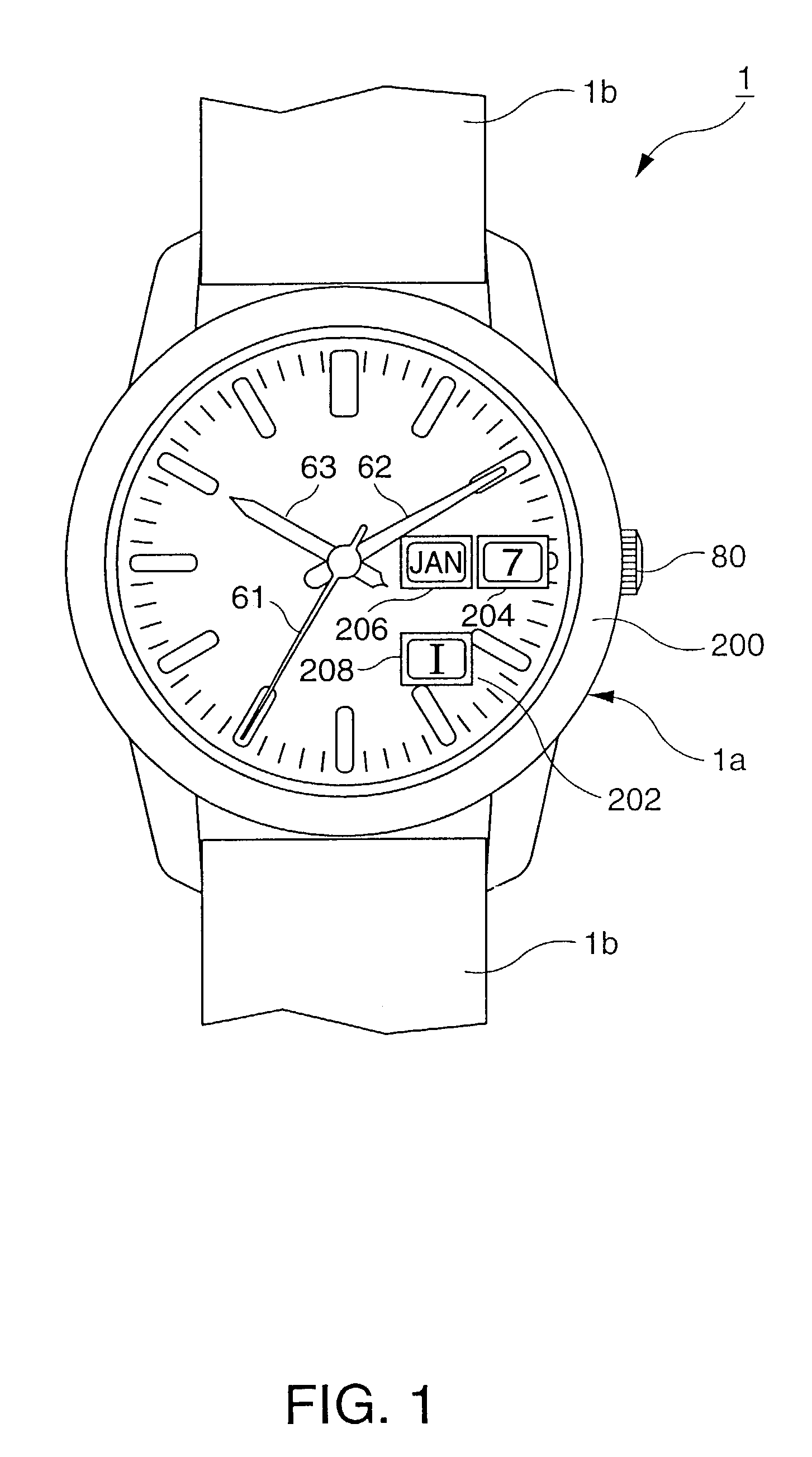
[0048]FIG. 1 shows the typical appearance of a wristwatch according to a preferred embodiment of the present invention. As shown in FIG. 1 this wristwatch 1 has a watch body 1a, and a band 1b attached to the watch body 1a. The watch body 1a has a case 200, a round dial 202 disposed in the case 200, and a crown 80 protruding from the case 200. Three display hands, that is, a seconds hand 61, a minutes (long) hand 62, and an hours (short) hand 63, are disposed above the dial 202. Symbols denoting the time are located at equal intervals around the circumference of the dial 202, and the current time is displayed by the numerals or symbols (these symbols could be letters) pointed to by the display hands.

[0049]A substanti...


PUM


Abstract

An electronic timepiece with date display function reduces power consumption in conjunction with the user adjusting the date, and makes it easier for the user to set the date. A displayed date detection unit H has a day detector H1 for detecting the displayed day, a month detector H2 for detecting the displayed month, and a year detector H3 for detecting the displayed year. A control unit A controls a calendar mechanism drive unit F according to the date detected by detectors H1 to H3.

Description

BACKGROUND OF THE INVENTION[0001]1. Field of the Invention[0002]The present invention relates to a timepiece having a date display function.[0003]2. Description of the Related Art[0004]A common date display mechanism used in wristwatches and other types of timepieces has a ring-shaped display panel called a day wheel. The numbers 1 to 31 are evenly spaced around the circumference of the day wheel, and the day wheel is rotationally driven linked to the gear train for rotationally driving the hour hand for displaying the hour. For example, when the hour hand is turned the equivalent of 24 hours by the gear train, the day wheel turns a distance equal to one day (that is, a 360 / 31 degree angle of rotation), and a number corresponding to the date is displayed in the date window provided in the dial of the wristwatch.[0005]A problem with this simple date display mechanism is that at the end of the month in months shorter than 31 days in the solar calendar (that is the short months of Febr...

Claims


Application Information

Patent Timeline
IPC IPC(8): G04B19/24G04C3/00G04C9/00G04C17/00G04G99/00
CPCG04C17/0066
Inventor KITAHARA, JOJIMATSUZAKI, JUN
Owner SEIKO EPSON CORP
Learn More