
Digital broadcasting receiver and method of controlling the same

a digital broadcasting receiver and receiver technology, applied in the field of digital broadcasting receivers, can solve the problems of incongruity and method not being friendly to users, and achieve the effect of not giving users a sense of incongruity

Inactive Publication Date: 2006-03-21
FUNAI ELECTRIC CO LTD
View PDF12 Cites 87 Cited by
  • Summary
  • Abstract
  • Description
  • Claims
  • Application Information

AI Technical Summary

Benefits of technology

The present invention provides a digital broadcasting receiver that can switch between one-channel and multi-channel broadcasts without giving the user a feeling of incongruity. The receiver includes a transport unit that separates / divids the broadcasting signal, a broadcast detecting unit that detects the type of broadcasting, and a subchannel control unit that controls the output of the broadcasting signal. The invention also provides a method for controlling the receiver by detecting the type of broadcasting and controlling the output of the broadcasting signal accordingly. The technical effect of the invention is to improve the user experience when selecting a subchannel.

Problems solved by technology

In the conventional method above, however, the user would feel a sense of incongruity because the display mode of the screen suddenly changes to display the divided windows in only the form of static images after the termination of the HD broadcasting.
Moreover, there can be the user's favorite subchannel in the HD broadcasting and the aforementioned method is never friendly as the user is required to select the subchannel while looking out the divided windows on the screen whenever the HD broadcasting is switched to the SD broadcasting.

Method used


Image

  • Digital broadcasting receiver and method of controlling the same
  • Digital broadcasting receiver and method of controlling the same
  • Digital broadcasting receiver and method of controlling the same

Examples


Embodiment Construction

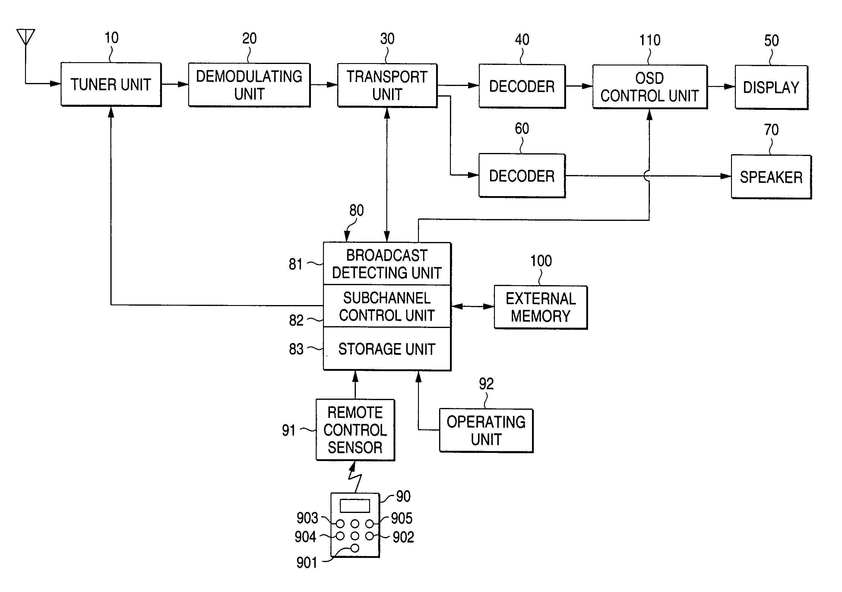
[0012]An embodiment of the present invention will now be described with reference to the drawings. FIG. 1 is a block diagram of a digital broadcasting receiver; and FIG. 2, a flowchart of a program to be processed by an MPU of the receiver.

[0013]The digital broadcasting receiver is a television receiver for receiving HD and SD broadcasting or ground waves in order to display the broadcast contents and has a circuit configuration as shown in FIG. 1.

[0014]In FIG. 1, reference numeral 10 designates a tuner unit for tuning and receiving a digital broadcasting signal; 20, a demodulating unit for demodulating an output signal of the tuner unit 10; and 30, a transport unit for separating / dividing a video signal, an audio signal and the like from an output signal of the demodulating unit 20.

[0015]The video signal outputted from the transport unit 30 is supplied to a display 50 via a decoder 40 and an OSD (On Screen Display) control unit 110. The OSD control unit 110 is a circuit, which is a...


PUM


Abstract

A digital broadcasting receiver capable of receiving HD (High Definition) broadcasting, SD (Standard Definition) broadcasting and the like. In the digital broadcasting receiver, a digital broadcasting signal subjected to demodulation is separated / divided in a transport unit before being supplied to decoders. Data on a packet ID included in the digital broadcasting signal is outputted from the transport unit. An MPU determines HD broadcasting or SD broadcasting according to the data on the packet ID and when the MPU determines the SD broadcasting, it instructs the transport unit to have a set subchannel displayed and also instructs an OSD control unit to make an OSD of the subchannel.

Description

BACKGROUND OF THE INVENTION[0001]1. Field of the Invention[0002]This invention relates to a digital broadcasting receiver which is utilized for receiving ground waves and the like, and more particularly to a digital broadcasting receiver capable of receiving HD (High Definition) broadcasting, SD (Standard Definition) broadcasting and the like, and to a method of controlling the digital broadcasting receiver.[0003]2. Description of the Related Art[0004]In the process of transition from analog to digital television broadcasting, a great diversity of broadcasting is increasingly attempted; for example, HD broadcasting utilizing a band equivalent to one channel and SD broadcasting utilizing several channels resulting from dividing the band equivalent to one channel. When the HD broadcasting that has been terminated is switched to the SD broadcasting of the same channel, the user naturally needs to select a subchannel of the SD broadcasting.[0005]There has been proposed a method of selec...

Claims


Application Information

Patent Timeline
Patent Type & Authority Patents(United States)
IPC IPC(8): H04N5/50H04N7/00H04B1/16H04H20/00H04H20/28H04H20/74H04H40/18H04H60/43H04H60/65H04N5/445H04N7/20
CPCH04N5/4401H04N5/445H04N7/015H04N21/482H04N21/4345H04N21/4347H04N21/4382H04N21/4383H04N21/4316H04N5/46H04N21/4221H04N21/4405H04N21/426
Inventor FUNAKOSHI, HIDEAKI
Owner FUNAI ELECTRIC CO LTD
Learn More