
Thermal printer and method determining battery condition based on temperature

a technology of temperature determination and printer, applied in typewriters, instruments, visual presentations, etc., can solve the problems of insufficient plate making width, power weakness corresponding to only the print width, and dc power

Inactive Publication Date: 2006-03-21
BROTHER KOGYO KK
View PDF35 Cites 8 Cited by
  • Summary
  • Abstract
  • Description
  • Claims
  • Application Information

AI Technical Summary

Benefits of technology

The apparatus effectively indicates power weakness conditions based on multiple usage factors, preventing print failures by ensuring the drive voltage remains above the determined weak voltage value, even under changing conditions.

Problems solved by technology

However, there exist various different factors which affect consumption of DC power other than the aforementioned print width and plate making width in the tape print apparatus for printing characters and the like on a print medium such as a tape, paper using heat generating devices provided on a thermal head and various kinds of the print apparatus.
Thus, determination of power weakness corresponding to only the print width and plate making width provides insufficient results.

Method used


Image

  • Thermal printer and method determining battery condition based on temperature
  • Thermal printer and method determining battery condition based on temperature
  • Thermal printer and method determining battery condition based on temperature

Examples


Embodiment Construction

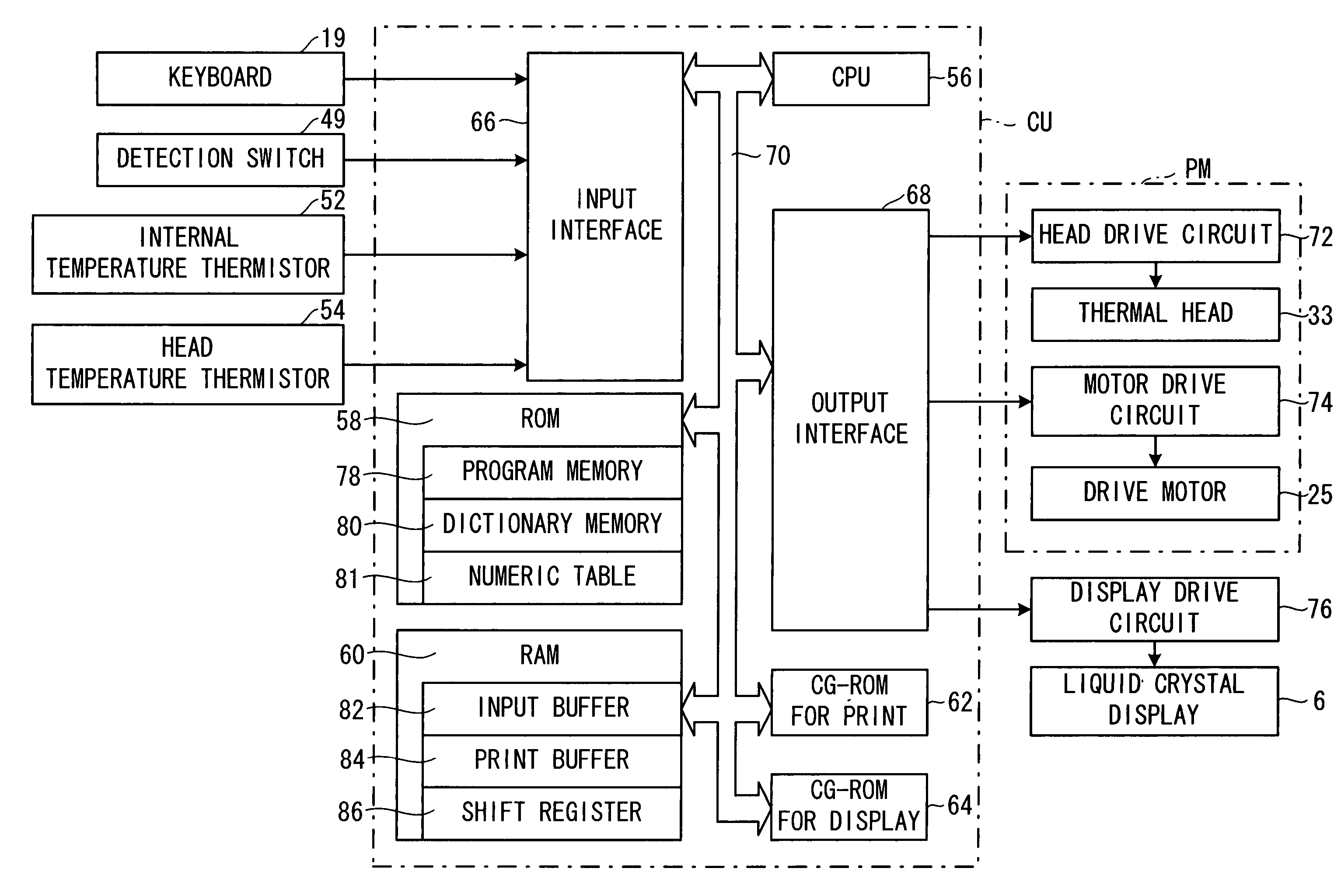
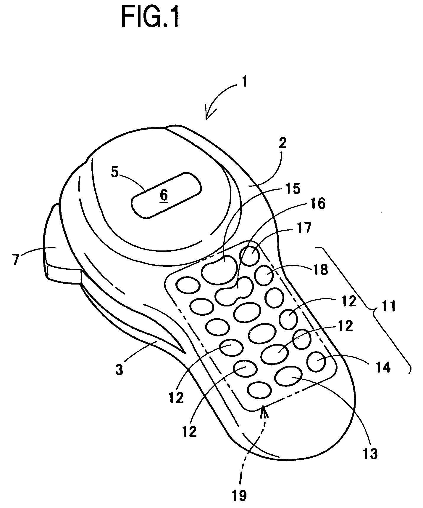
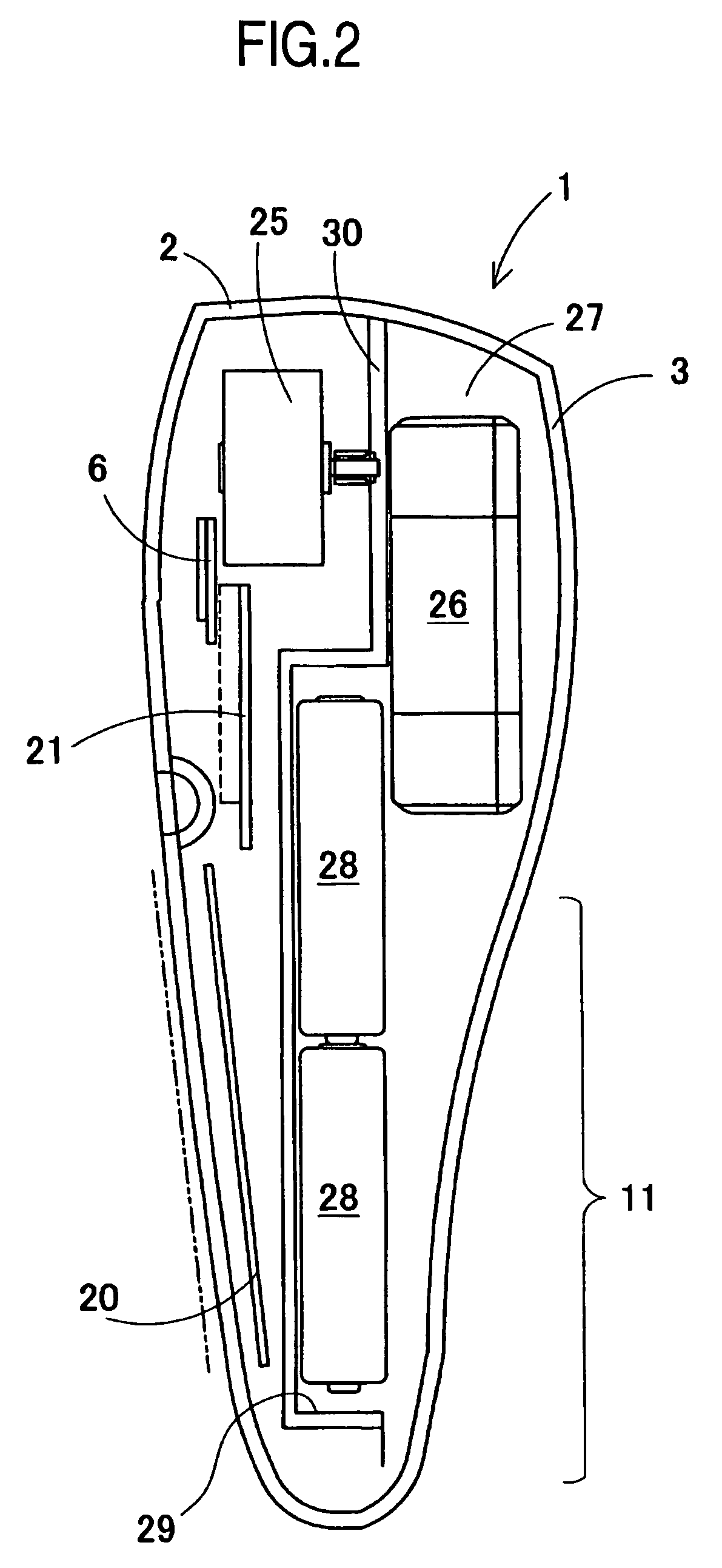
[0036]Hereinafter, a tape print apparatus according to an exemplary embodiment of the present invention will be described in detail with reference to the accompanying drawings. First, the schematic structure of the tape print apparatus of this embodiment will be described with reference to FIGS. 1 and 2.

[0037]As shown in FIGS. 1 and 2, a tape print apparatus 1 includes a main body 2 made of any suitable material such as synthetic resin and a rear face cover 3 made of any suitable material such as synthetic resin which is mounted on the rear face (an opposite face to a face opposing an operator when the tape print apparatus 1 is used) of the main body 2. An upper, substantially half section in the length direction of the main body 2 is formed slightly round in its horizontal view and a window section 5 laterally long in the right and left direction is made substantially in the central section of this upper side surface and a display, such as, e.g., liquid crystal display 6 is dispose...


PUM


Abstract

A tape print apparatus is capable of setting a weak voltage value, serving as a criterion on indicating a power weakness condition on a display, to an appropriate voltage value based on various kinds of usage conditions by considering that the degree of consumption of drive power differs depending on the usage conditions of a tape print apparatus.

Description

BACKGROUND OF THE INVENTION[0001]1. Field of Invention[0002]The present invention relates to a portable tape print apparatus in which a tape cassette incorporating a long tape is accommodated, a platen roller is driven by a drive motor using a drive power source such as a battery and a heat generating device of a thermal head is heated according to print data to print on the tape and discharge it to the outside, and more particularly a print apparatus capable of indicating an appropriate weak battery condition corresponding to various different usage conditions considering that the degree of consumption of the drive power source differs depending on the usage condition of the tape print apparatus.[0003]2. Description of Related Art[0004]If a voltage supplied from a DC power supply in a print apparatus such as a tape print apparatus which is driven by the DC power supply (e.g. a battery) drops below a predetermined voltage value, various problems relating to printing and control occu...

Claims


Application Information

Patent Timeline
Patent Type & Authority Patents(United States)
IPC IPC(8): B41J11/44B41J1/54B41J29/46B41J2/325B41J3/407B41J29/38B41J29/42G06K15/02
CPCB41J29/38B41J3/407G06K15/028G06K15/022
Inventor NAGAE, TSUYOSHIHORIUCHI, TAKASHI
Owner BROTHER KOGYO KK
Learn More