
Method for positioning the slitters of a slitter-winder in a paper or board machine

a technology of paper or board machine and slitterwinder, which is applied in the field of positioning the slitterwinder in the paper or board machine, can solve the problems of obstructing movement and the slitterwinder cannot remain unmoved, and achieve the effect of significantly shortening the movement time of the slitterwinder

Inactive Publication Date: 2006-03-14
VALMET TECH INC
View PDF34 Cites 5 Cited by
  • Summary
  • Abstract
  • Description
  • Claims
  • Application Information

AI Technical Summary

Benefits of technology

[0009]An object of the invention is to provide a method for positioning the slitters of a slitter-winder in a paper or board machine by which the movement time of the slitters is significantly shortened even to a few seconds.
[0011]In accordance with the invention, in positioning of the slitters of a slitter winder, at least one slitter which is not in use is moved to a new slitting position and / or to a waiting position for the next slitting position while the other slitters are cutting the web. The waiting position is an advance movement position from which the slitter can be moved during the actual movement to a new slitting position in connection with other movements such that it most preferably does not cause further stops but can be placed in position simultaneously with another / other slitters. The waiting position can be from a slitter position before an advance movement towards a new slitting position or backwards. The slitters selected for an advance movement are most appropriately moved to a new slitting position or to a waiting position, for example, to the middle area of the movement area to a correct location such that, when stopping at a desired slitting position in connection with the next movement, during one stop of the transfer device of the slitters it is possible to place several slitters in a correct new slitting position. In addition, an object of the invention is to provide a method in which the movement distance is as short as possible.
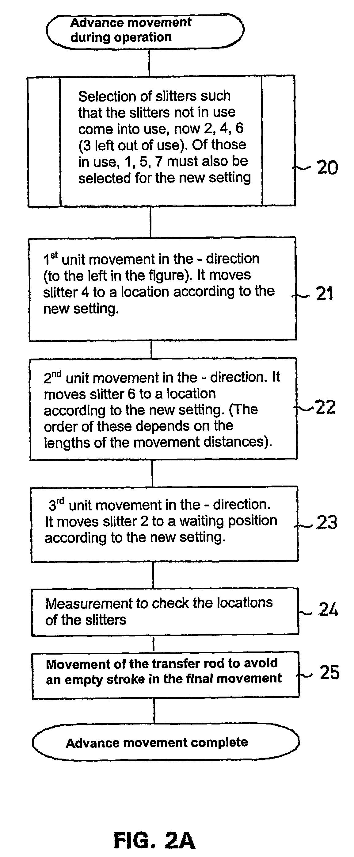
[0015]In accordance with the invention, by means of advance movement, a method is provided which enables the time needed for positioning the slitters in a slitter-winder to be minimized. To minimize the movement time, the number of movements is kept to the minimum and those movements are made in advance which can be made while operating according to the preceding slitter setting. Those slitters which are included in the preceding slitter setting, can, of course, not be moved during the advance movement, but, instead, they are moved, when needed, in connection with the actual movement.
[0016]An object of the invention is to minimize the slitter movement time and it is achieved by means of advance movement in which, while still operating according to the preceding slitter setting, all those movements are completed which can be made without disturbing the running operation. In the prior art, all movements are made only after the last set of the preceding slitter setting has been discharged and the slitter-winder has stopped. The slitter movement time in arrangements according to the prior art is one minute on average. When accomplished by the method according to the invention, the slitter movement time is 10 s on average in tests, which means that the saving of time attainable by the invention is very significant.
[0019]A slitter which is in use may prevent the movement of some slitter according to a new slitter setting all the way to the end, in which case that slitter is moved in an advance movement to another suitable waiting position.
[0022]A measurement for verifying the location of the slitters is made before advance movement if the locations of the slitters are not known. After the advance movement, a verifying measurement is made to check the locations of the slitters. If needed, the measurement-movement-measurement sequence is repeated to correct the errors so that they shall be within tolerances. Thus, the advance movement also has the advantage that the final movement can be started without a preliminary verifying measurement.

Problems solved by technology

In most cases, however, these slitters cannot remain unmoved, because otherwise they might obstruct the movement of the slitters which will be used.

Method used


Image

  • Method for positioning the slitters of a slitter-winder in a paper or board machine
  • Method for positioning the slitters of a slitter-winder in a paper or board machine
  • Method for positioning the slitters of a slitter-winder in a paper or board machine

Examples


Embodiment Construction

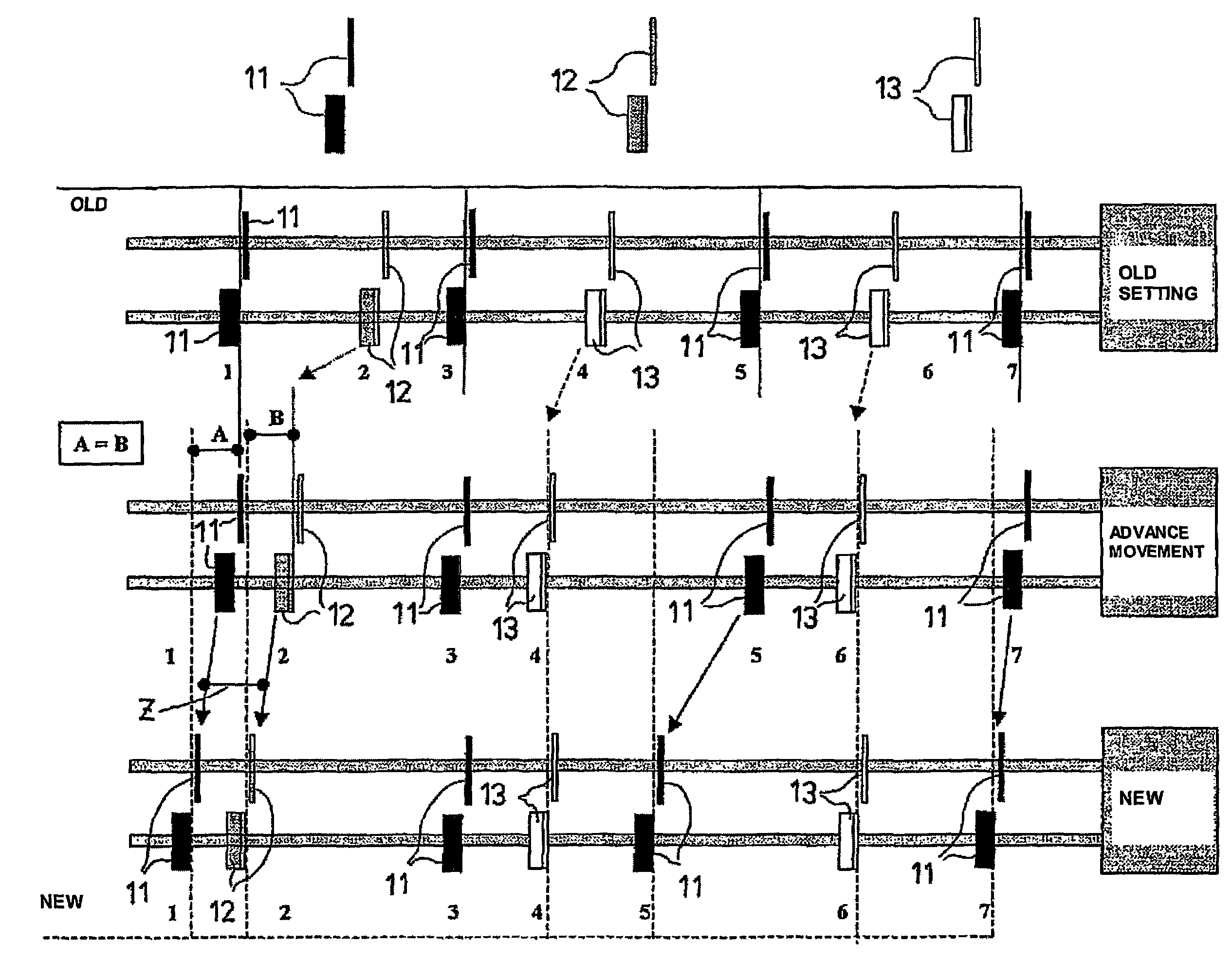
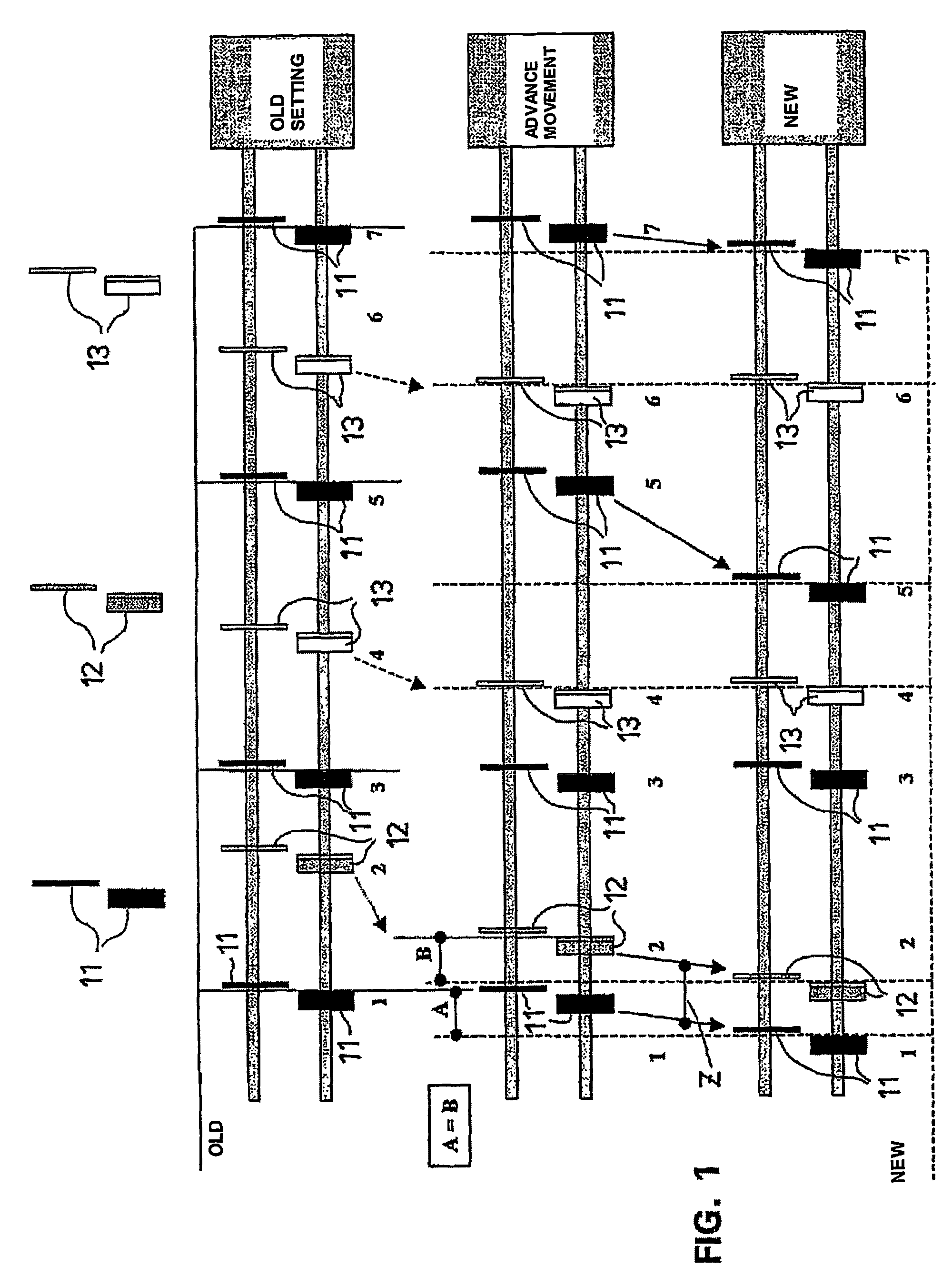
[0028]FIG. 1 shows a case in which a machine comprises seven slitters. The slitters according to an old setting are denoted with the reference numeral 11 and with a black colour, the slitters moved to a waiting position in an advance movement are denoted with the numeral 12 and with a grey colour, and the slitters moved to a new slitting position in an advance movement are denoted with the reference numeral 13 and with a white colour. In the preceding setting (OLD SETTING) there are four cuts (three rolls), in which connection three slitters are not in use. A new setting comprises six cuts, in which connection only one slitter remains unused. The slitters 1, 5, 7 are in use in the preceding (OLD) setting and in the new setting, the slitter 3 is in use only in the preceding (OLD) setting. The slitters 4 and 6 can be moved to their positions already in an advance movement, the slitter 2 must be moved to a waiting position, in which its movement distance will be the same as that of the...


PUM

PropertyMeasurementUnit
Lengthaaaaaaaaaa
Widthaaaaaaaaaa

Abstract

The slitters of a slitter-winder in a paper or board machine are placed in position in slitting to slit component webs to the desired width. The slitters are moved to a new slitting position as a normal movement when the slitter-winder has stopped after slitting according to the preceding slitter setting. In positioning the slitters, at least one slitter not in use in the slitter-winder is moved before the normal movement as an advance movement to a new slitting position and / or to a waiting position for the next slitting position while the other slitters are slitting the web.

Description

CROSS REFERENCES TO RELATED APPLICATIONS[0001]This application is a U.S. national stage application of International Application No. PCT / FI02 / 0045, and claims priority on Finnish Application No. 20011005, filed May 14, 2001.STATEMENT AS TO RIGHTS TO INVENTIONS MADE UNDER FEDERALLY SPONSORED RESEARCH AND DEVELOPMENT[0002]Not applicable.BACKGROUND OF THE INVENTION[0003]The invention relates to a method for positioning the slitters of a slitter-winder in a paper or board machine, in which method the slitters of the slitter-winder are placed in position in slitting to slit component webs to the desired width, in which method the slitters are moved to a new slitting position as a normal movement when the slitter-winder has stopped after slitting according to the preceding slitter setting.[0004]With respect to the prior art, reference is made to FI patent 68 185, which describes a method for determining the position of a movable device or a member of this device and / or for determining a c...

Claims


Application Information

Patent Timeline
IPC IPC(8): B26D1/00B27B5/34B26D7/26B26D11/00
CPCB26D7/2635B26D11/00B65H2301/41482Y10T83/7826Y10T83/05Y10T83/659Y10T83/7876Y10T83/04
Inventor KOUTONEN, PAULIPAANASALO, JARI
Owner VALMET TECH INC
Learn More