
Method for detecting and representing one or more objects, for example teeth

a technology for detecting objects and objects, applied in boring tools, dental prosthetics, television systems, etc., to achieve the effect of improving recognition accuracy

Inactive Publication Date: 2006-03-07
SIRONA DENTAL SYSTEMS
View PDF20 Cites 96 Cited by
  • Summary
  • Abstract
  • Description
  • Claims
  • Application Information

AI Technical Summary

Benefits of technology

[0011]In order to measure an object from different directions or distances, and to be able to detect undercuts and / or to extend the depth measurement range and / or to increase the accuracy by averaging, the first recording is carried out by applying the method according to the invention. What is achieved is that during the second and, if appropriate, further recording, only the viewing angle and the distance from the object are varied but the object always appears in approximately the same position on the image. This produces an advantageous starting position for the automatic, exactly calculated correlation.
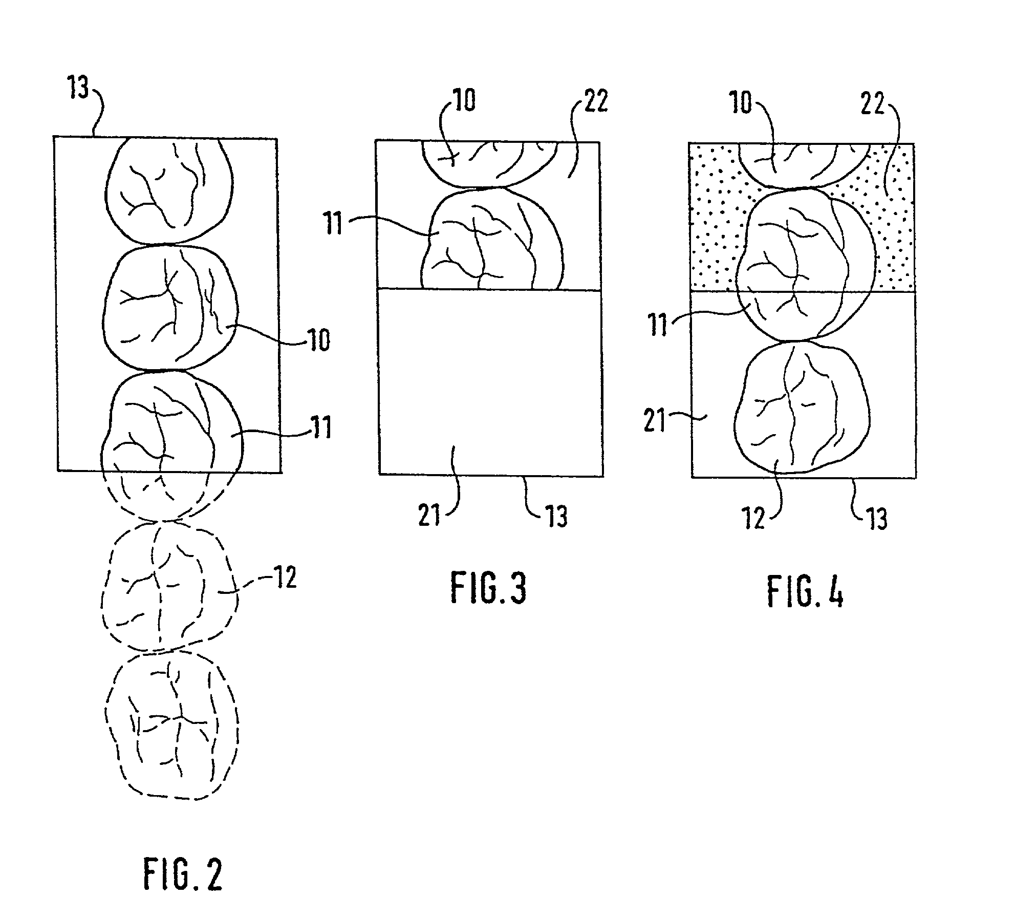
[0013]By virtue of the fact that the object to be recorded in the second image has been altered relative to the object recorded in the first image, the surroundings of the altered object having remained essentially unchanged. This process makes it possible to document restorations and to detect changes to the restorations.
[0014]If the intention is to measure objects which are more extensive than the measurement zone of the camera, part of the object can be measured in a first position of the camera. Afterward, a second measurement recording is created, which covers part of the area of the first measurement recording but also captures a new part of the object. In this case, the still image is displaced by a predetermined distance and / or a predetermined angle and is thus superposed on the moving search image only in a sub-area. Using the area of overlap, the two measurement recordings are coarsely correlated by the method according to the invention, and exactly correlated according to automatic methods known per se. As a result, it is possible for successively recorded sub-images of a complete jaw to be strung together exactly and thus for a dental arch as a whole to be detected and measured.
[0016]The displacement and / or rotation are advantageously effected in a manner dependent on the area to be recorded using knowledge about the image information to be expected from the object to be recorded for the second image. This knowledge may be information determined from statistical evaluations or from individual peculiarities typical of the object. This means that manual displacement is unnecessary, as a result of which the operability is improved.
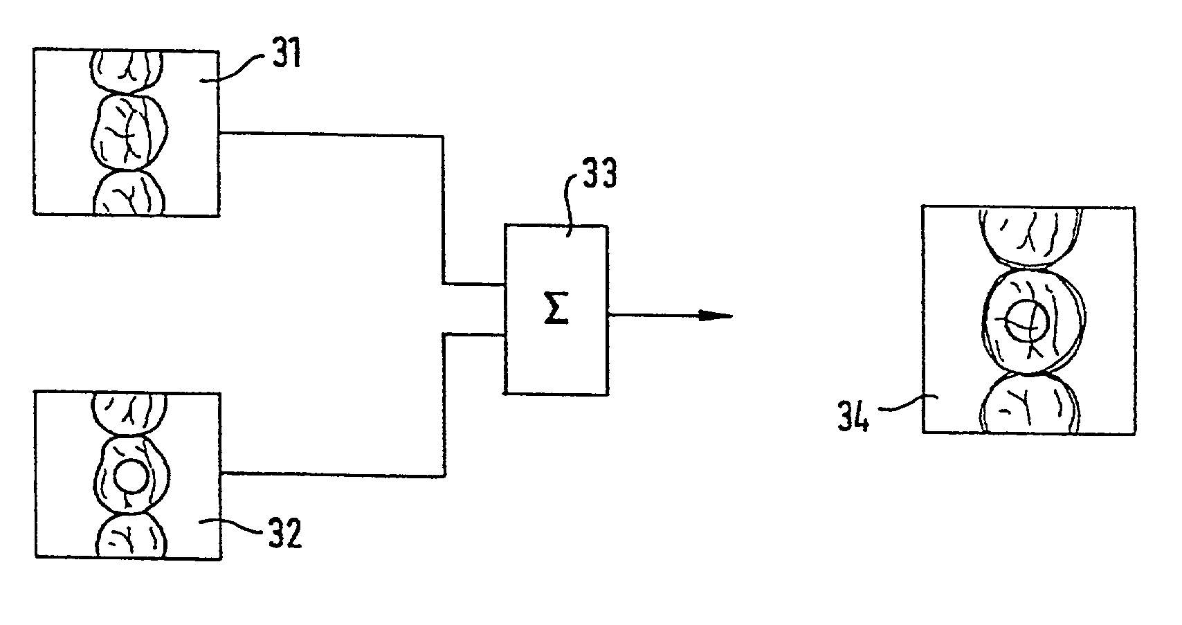
[0022]It may be advantageous if the first image is not superposed directly, but rather as modifications thereof. Such modifications generated by image-processing means allow for the recognition accuracy to be improved.

Problems solved by technology

However, software methods of this type function only when the relative position of the images is adequately known as a result of previous measures, i.e., the images must be coarsely correlated with one another.
This is disadvantageous, particularly when different recordings of the same tooth and of its surroundings have to be correlated with one another, or when rows of teeth have to be recorded over a plurality of recordings.

Method used


Image

  • Method for detecting and representing one or more objects, for example teeth
  • Method for detecting and representing one or more objects, for example teeth
  • Method for detecting and representing one or more objects, for example teeth

Examples


Embodiment Construction

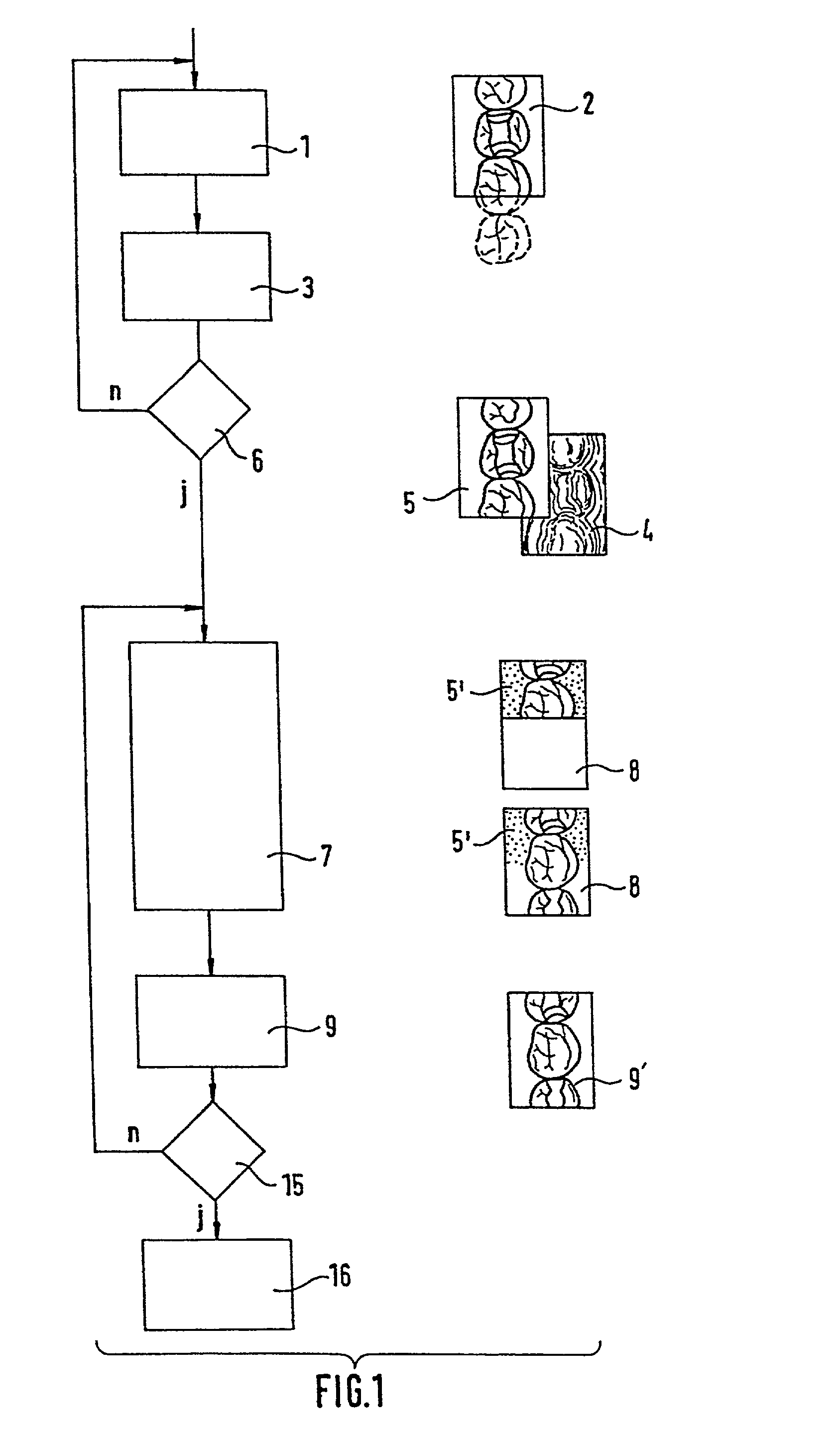
[0032]The first recording, already described in EP 0 250 993 B1, is initiated by a search phase preceding the actual measurement operation. This process is shown in accordance with the flow diagram from FIG. 1. In this search phase 1, a measurement camera initially operates like a conventional video system. The tooth part which appears in the recording window is registered by an imaging optical system and sensor, and is represented on a monitor as a standard television image 2. The observed tooth is illuminated by the camera for the purpose of spatial measurement, to be precise with a grid-like reference pattern. However, this reference pattern should not also appear on the search image, since the actual image content is thereby superposed. Therefore, the pattern is eliminated. The camera is oriented using the video search image in such a way that the measurements required for the measurement operation can be carried out successfully. If the production of a fitting for a tooth recon...


PUM


Abstract

A method for detecting and representing one or more objects, such as teeth, their preparations and their immediate environment, using a camera. A first recording is made wherein a still image is produced. The still image is blended into a current, mobile search image in at least one sub-area in the second step, so that both images are recognizable. In the third step, the camera is positioned in such a way that the search image overlaps the blended-in still image in at least one sub-area. The second recording process is initiated in a fourth step.

Description

BACKGROUND OF THE INVENTION[0001]The invention relates to a method for detecting and representing one or more objects, for example teeth or their preparations and their immediate vicinity, using a camera for obtaining three-dimensional data. These data can be used for producing a fitting.DESCRIPTION OF THE RELATED ART[0002]EP 0 250 993 B1 discloses a method for spatially recording and representing teeth, their preparations and their immediate vicinity using a camera for obtaining three-dimensional data. The data is used for producing a fitting. In order to determine the suitable recording position of the camera, a reference pattern is projected to obtain data depth. First, however, a moving video search image is generated and displayed on a monitor on which the projected reference pattern does not appear. If the camera is in the desired recording position, then in response to an initiation command, an image recording sequence will proceed for generating and storing a data record. Th...

Claims


Application Information

Patent Timeline
Patent Type & Authority Patents(United States)
IPC IPC(8): G06K9/00A61C19/04A61B1/24A61C9/00A61C13/00H04N5/232H04N7/18
CPCA61C9/00A61C13/0004A61C9/004A61C9/0053
Inventor PFEIFFER, JOACHIMWEDLER, VOLKERORTH, ULRICHPIEPER, REINHARD
Owner SIRONA DENTAL SYSTEMS
Learn More