Position detecting method, information recording/reproducing device and information recording medium

a technology of information recording/reproducing device and position detection method, which is applied in the direction of recording signal processing, maintaining head carrier alignment, instruments, etc., can solve the problems of waste of method, poor usability of position information signal pattern, and error in head position signal to be detected

Inactive Publication Date: 2006-03-07
KK TOSHIBA
View PDF6 Cites 21 Cited by
  • Summary
  • Abstract
  • Description
  • Claims
  • Application Information

AI Technical Summary

Benefits of technology

[0009]It is an object of the present invention to provide a position detecting method, an information recording / reproducing device, and an information recording medium which are capable of obtaining a position detected signal of a head without an error even if a shift occurs in a servo pattern recorded into a medium.
[0045]In the position information signal pattern, the position signals obtained in the two frequencies are designated by Pa and Pb. The shifts of the pattern in the circumferential and radial directions are designated by ΔX and ΔY, and the errors of the position signals are designated by ΔPa and ΔPb. When slope in the line group where the position signals are subject to be calculated are designated by −ra and −rb,ΔPa=−ΔY−raΔXΔPb=−ΔY−rbΔX.A new position signal is created as follows:P=kPa+(l−k)·Pb.Variance of an error of this position signal becomes as follows:V(ΔP)=V(ΔX)[{k(ra−rb)+rb}+E(ΔXΔY) / V(ΔX)]2+V(ΔY)−{E(ΔXΔY)}2 / V(ΔX).E( ) represents an average, and V( ) represents variance here. When the shifts in the circumferential direction and the radial direction of the servo pattern do not correlate with each other, namely, whenE(ΔXΔY)=0,the coefficient k is set tok=rb / (rb−ra)As a result,V(ΔP)=V(ΔY)so that the error of the pattern in the circumferential direction can be eliminated by using the two position signals Pa and Pb. As a result, the position signal , which has high usability of the servo pattern and is not influenced by the shift of the pattern in the circumferential direction, can be obtained.

Problems solved by technology

When the servo pattern is shifted, however, an error occurs in a head position signal to be detected.
For this reason, the usability of the position information signal pattern is not good, and thus this method is wasteful.
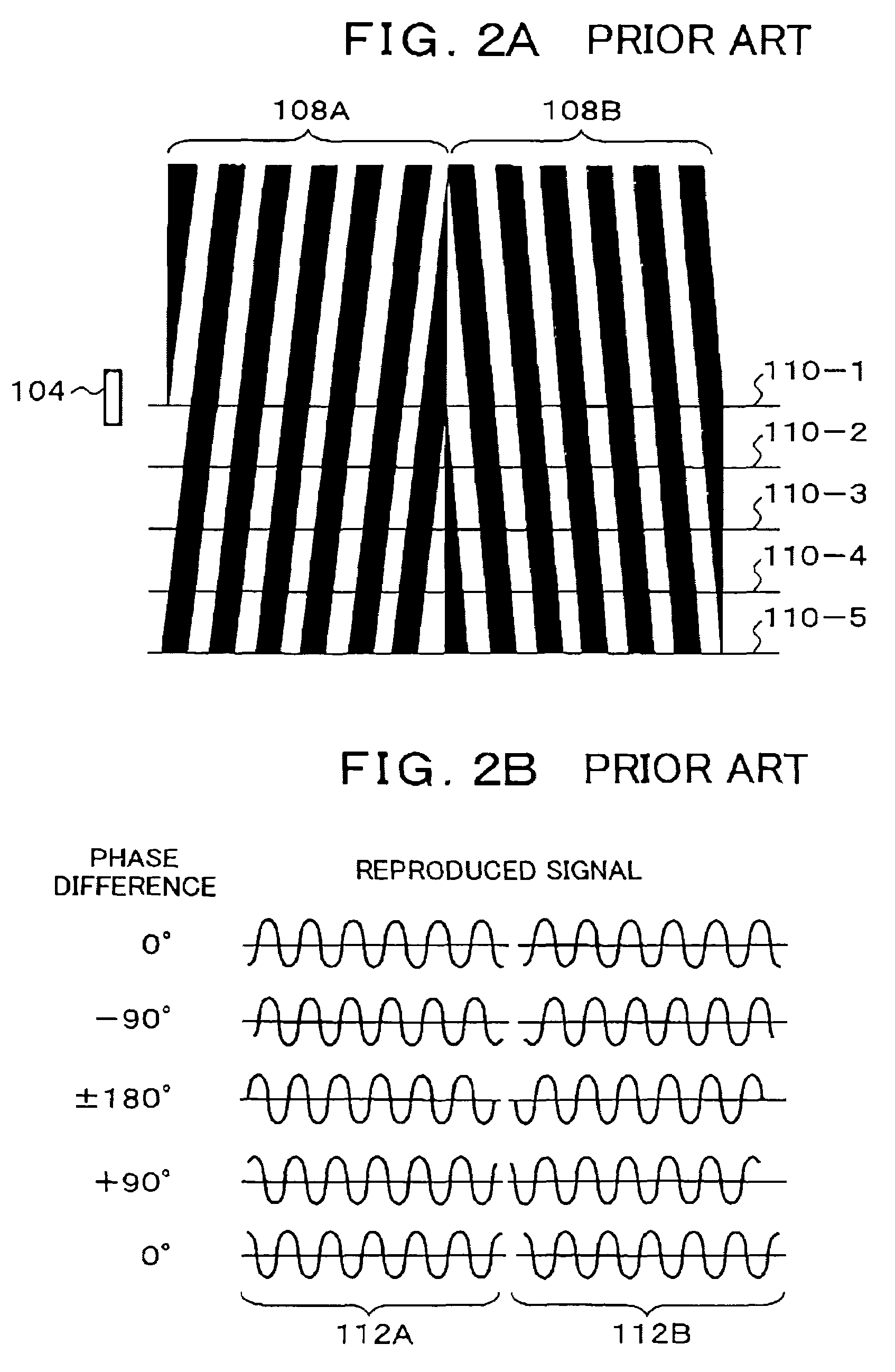
In the case of the phase demodulating method, the shift of the servo pattern in the radial direction is directly an error of the position signal of the head.
Further, the shift in the circumferential direction is also a phase shift of a reproduced signal, and thus becomes an error of the position signal.
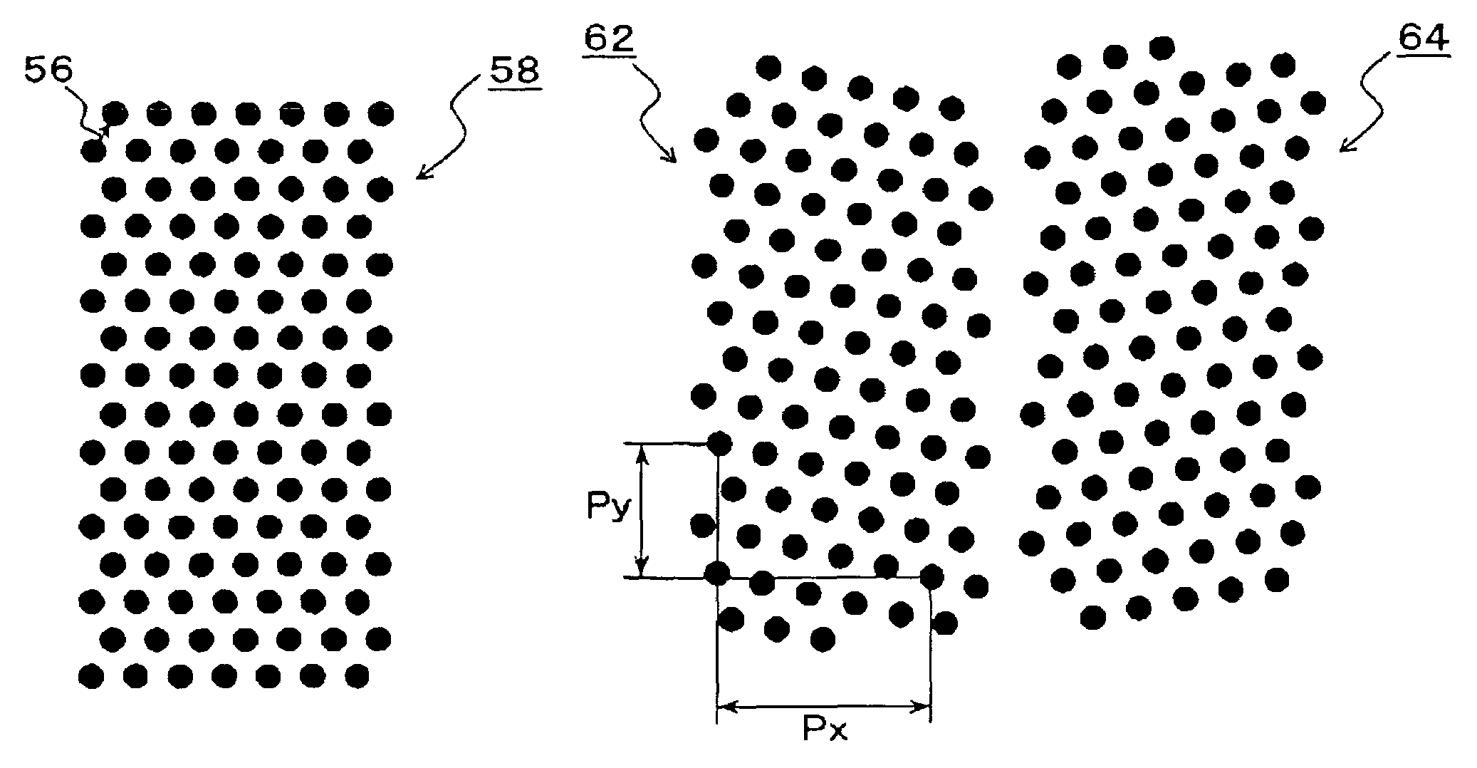
When an inclination is set down so that the lines face the circumferential direction, (Py / Px) becomes small, but as a result, the amplitude of the reproduced signal becomes small, and the error of the position signal is enlarged due to deterioration of SN ratio.
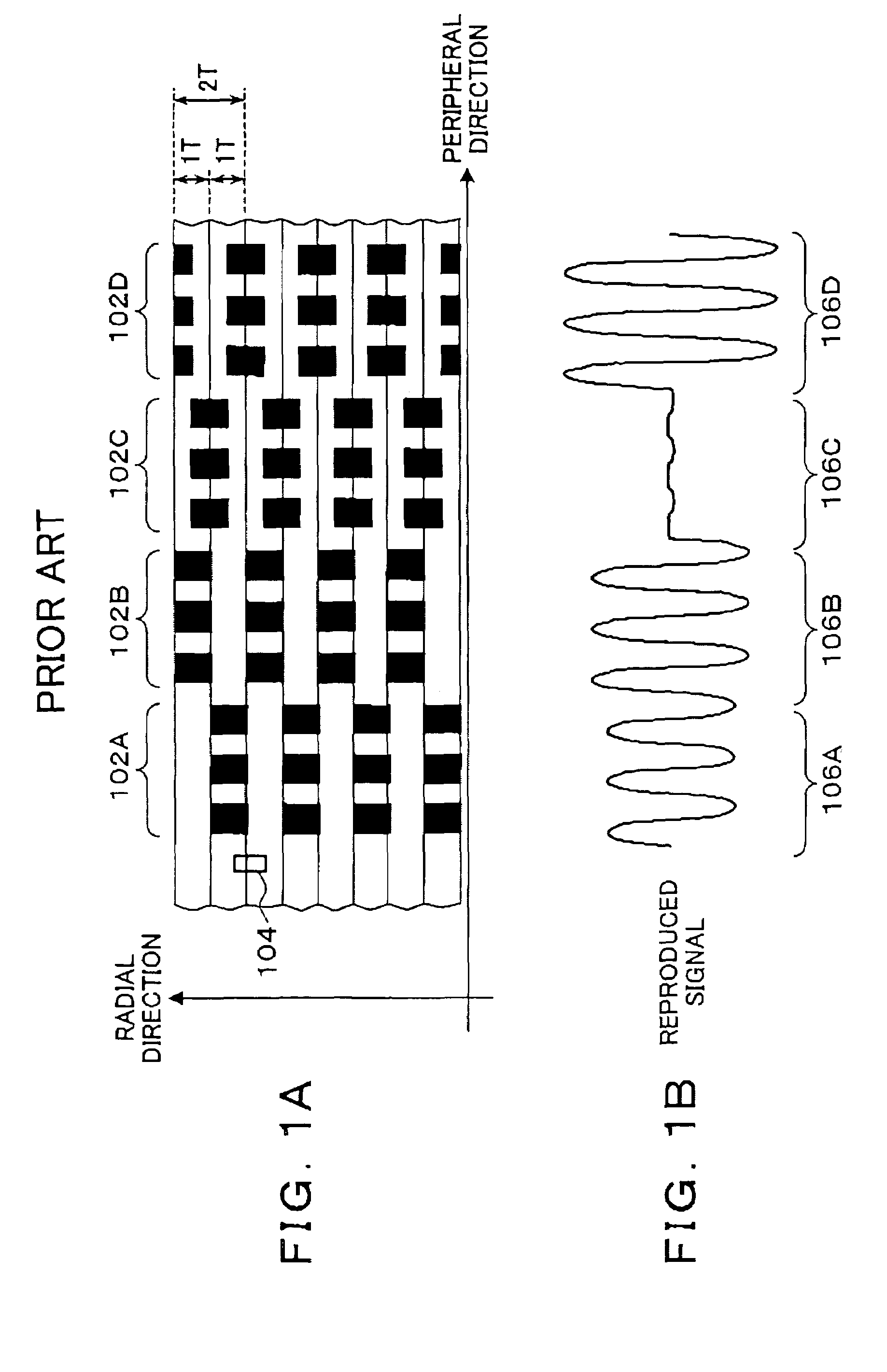
The amplitude demodulating method has a problem that the usability of the servo pattern is not good, whereas the phase demodulating method has a problem that the shift of the pattern in the circumferential direction influences accuracy of the position signal.

Method used


Image

  • Position detecting method, information recording/reproducing device and information recording medium
  • Position detecting method, information recording/reproducing device and information recording medium
  • Position detecting method, information recording/reproducing device and information recording medium

Examples


Embodiment Construction

[0059]FIG. 3 is an explanatory diagram of servo writer facility for creating a position information signal pattern of the present invention and recording it into a disc. In FIG. 3, the servo writer facility is composed of a servo pattern creating device 10 and a servo writer 12. The servo pattern creating device 10 creates a servo pattern of the present invention according to a procedure shown in a flowchart of the servo pattern creating process in FIG. 5. When the servo pattern creating device 10 creates the servo pattern of the present invention, parameters of the pattern creation are set so that various patterns are preset to be stored. A servo pattern to be used is selected as the need arises so as to be supplied to the servo writer 12. The servo writer 12 is provided with a head 18, and an HDD assembly 14 is set on the head 18. The servo writer 12 writes servo pattern of the present invention provided from the servo pattern creating device 10 into discs 16-1 and 16-2. In the em...


PUM

PropertyMeasurementUnit
angleaaaaaaaaaa
frequencyaaaaaaaaaa
frequenciesaaaaaaaaaa

Abstract

A position information signal pattern is recorded into a recording medium. The position information signal pattern is configured by arranging graphics having a circular shape, a rectangular shape or the like surrounded by a certain closed curve as pattern elements on a plane, and arranging the pattern elements in circumferential and radial directions of a disc so that a phase and a head position establish a proportional relationship in two or more frequency components of a reproduced signal. Position signals of the two frequency components included in the reproduced signal from the position information signal pattern are obtained, and the two position signals are added up with a certain ratio so that a position signal without error is obtained.

Description

[0001]This is a continuation of International PCT Application No. PCT / JP01 / 06915 filed Aug. 10, 2001.BACKGROUND OF THE INVENTION[0002]1. Technical Field[0003]The present invention relates to a position detecting method, an information recording / reproducing device and an information recording medium which are used for detecting a head position according to a servo pattern and locating the head at the time of recording / reproducing. Particularly the invention relates to the position detecting method, the information recording / reproducing device and the information recording medium which are used for detecting the head position accurately even if recording shift occurs in the servo pattern.[0004]2. Description of the Related Arts[0005]At the present, in a head locating control method which is called as sector servo used in a magnetic disc device, servo areas where servo information is recorded are radially arranged on a disc with an equal angle. A head is located on a target track based...

Claims


Application Information

Patent Timeline
Patent Type & Authority Patents(United States)
IPC IPC(8): G11B5/02G11B5/596
CPCG11B5/59655
Inventor SHIMATANI, KEIJI
Owner KK TOSHIBA
Why Eureka
Try Eureka