Image processing method, apparatus, recording medium and chart therefor
a chart and image processing technology, applied in the field of image processing methods for reading charts, can solve the problems of inability to achieve highly precise calibration of printer apparatuses, and the calibration of scanning apparatuses for stabilizing and optimizing characteristics of such apparatuses has not been conventionally executed, so as to achieve constant calibration of image forming units
- Summary
- Abstract
- Description
- Claims
- Application Information
AI Technical Summary
Benefits of technology
Problems solved by technology
Method used
Image
Examples
first embodiment
[0046]FIG. 1 is a block diagram showing the configuration of a printer calibration system constituting the present embodiment.
[0047]In the present embodiment, the form of connection in the network and the protocol therein are not particularly referred to, but there may be adopted any connection form and protocol in a similar manner.
[0048]Referring to FIG. 1, a software realizing the present system is installed in a server PC 1, which is connected to a network 5.
[0049]A scanner calibration data storage unit 11 stores scanner calibration data (explained in more detail later) stored in the server PC 1.
[0050]A printer 2 connected to the network 5 is subjected to the calibration in the present system, and is rendered capable of printing operation from instructions from plural PC's connected on the network. A calibration data storage unit 21 provided in the printer 2 is used for storing calibration data to be explained later, when such data are downloaded from the PC 1.
[0051]A scanner 3 c...
second embodiment
[0096]In the following there will be given a detailed explanation of a second embodiment of the present invention.
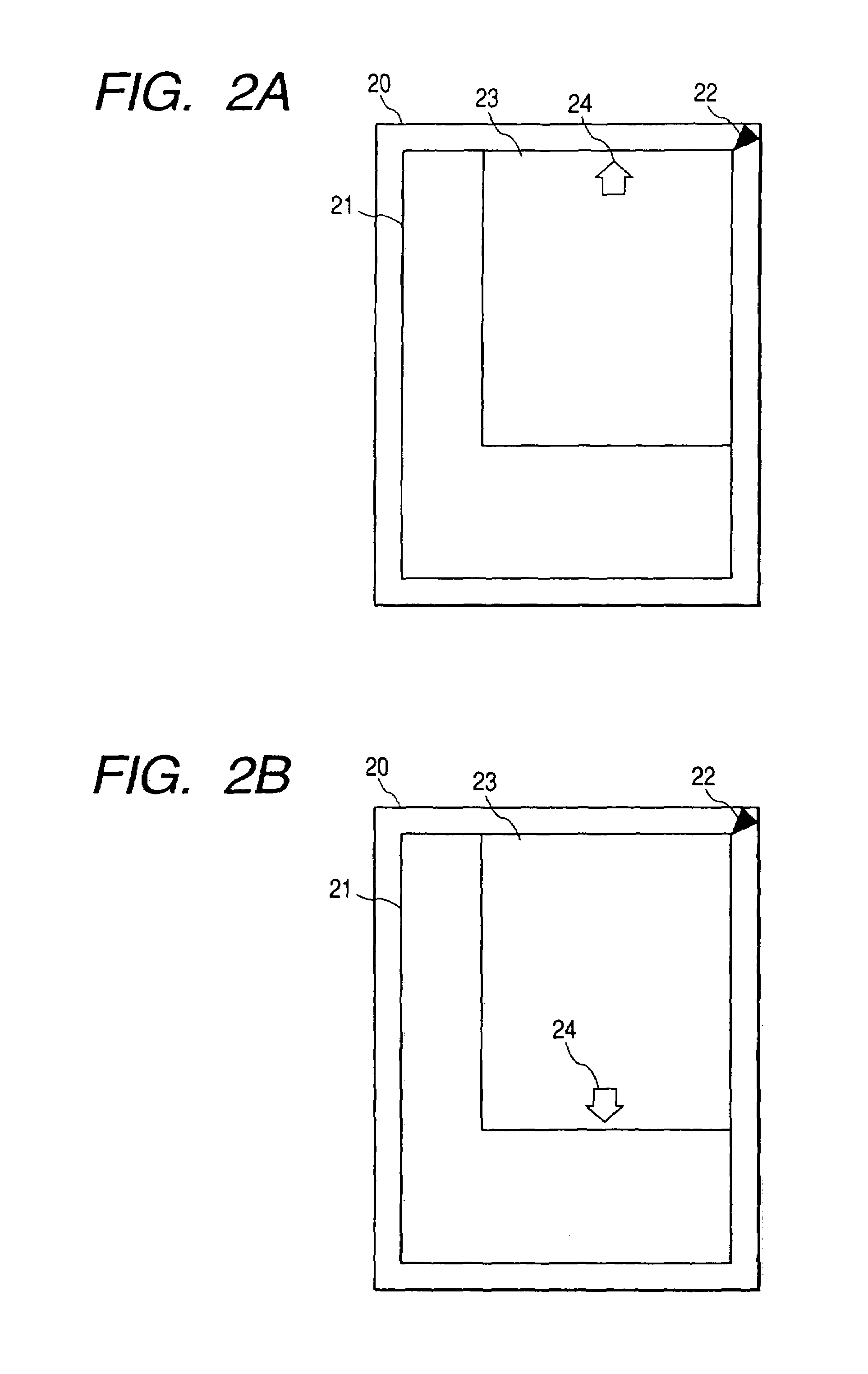
[0097]In contrast to the first embodiment designed to execute automatic discrimination and to provide error display in case the scanner chart and the printer chart to be used in the calibration are erroneously used by an operation error of the user, the second embodiment is so designed as to detect an inverse placement of the two charts on the original supporting table of the scanner by an operation error of the user and to execute a process same as in the case where the charts are properly placed.
[0098]Consequently, the printer calibration apparatus of the second embodiment is same in the basic configuration as the first embodiment, but is different in detecting the inverse placement of the two charts on the original supporting table of the scanner and executing data processing in a same manner as in the case of proper placement, and also in the control method thereof.
[...
third embodiment
[0111]In the following there will be given a detailed explanation on a third embodiment of the present invention.
[0112]In contrast to the first embodiment designed to execute automatic discrimination and to provide error display in case the scanner chart and the printer chart to be used in the calibration are erroneously used by an operation error of the user, the third embodiment is so designed as to detect a skewed placement of the two charts on the original supporting table of the scanner by an operation error of the user and to execute an error display.
[0113]Consequently, the printer calibration apparatus of the third embodiment is same in the basic configuration as the first embodiment, but is different in detecting the skewed placement of the two charts on the original supporting table of the scanner and executing an error display, and also in the control method therefor.
[0114]In the following there will be explained portions different from the first embodiment.
[0115]The confi...
PUM
 Abstract
Description
Claims
Application Information
 - Generate Ideas
- Intellectual Property
- Life Sciences
- Materials
- Tech Scout
- Unparalleled Data Quality
- Higher Quality Content
- 60% Fewer Hallucinations
Browse by: Latest US Patents, China's latest patents, Technical Efficacy Thesaurus, Application Domain, Technology Topic, Popular Technical Reports.
© 2025 PatSnap. All rights reserved.Legal|Privacy policy|Modern Slavery Act Transparency Statement|Sitemap|About US| Contact US: help@patsnap.com


