
Flow distributor of an electrically heated cigarette smoking system

a technology of flow distributor and electrical heating, which is applied in the direction of tobacco pipes, tobacco, food science, etc., can solve the problems of limited pyrolysis of cigarettes, limited total particulate matter produced in the generated aerosol, and limited air flow over a limited area of the heater, so as to increase the total aerosol delivery of the system

Active Publication Date: 2006-02-07
PHILIP MORRIS USA INC
View PDF9 Cites 189 Cited by
  • Summary
  • Abstract
  • Description
  • Claims
  • Application Information

AI Technical Summary

Benefits of technology

[0007]An embodiment according to the present invention provides a desirable improvement in air flow distribution to heater blades of an electrical smoking system, which results in an increase of the total aerosol delivery of the system.

Problems solved by technology

It has been discovered that side holes through the sleeve surrounding the heater blades may result in channeling of the air flow over a limited area of the heater.
With limited air flow to the heater blades and the cigarette, the pyrolysis of the cigarette is also limited and the total particulate matter produced in the generated aerosol is restricted.
Accordingly, limitations in the air flow to the heater blades can result in the heater failing to produce sufficient aerosol to provide a smoker with the desired flavors and aromas.

Method used


Image

  • Flow distributor of an electrically heated cigarette smoking system
  • Flow distributor of an electrically heated cigarette smoking system
  • Flow distributor of an electrically heated cigarette smoking system

Examples


Embodiment Construction

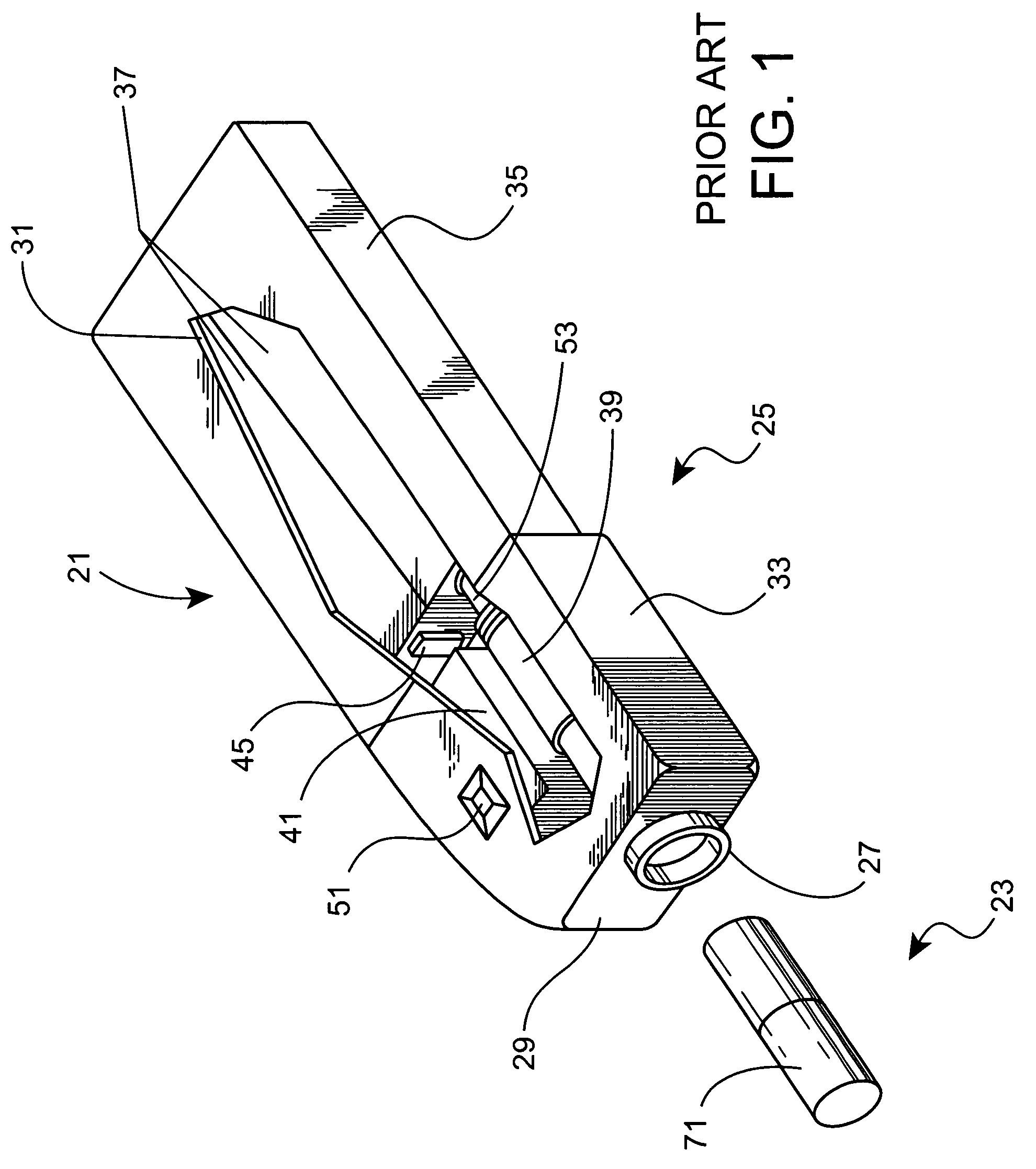
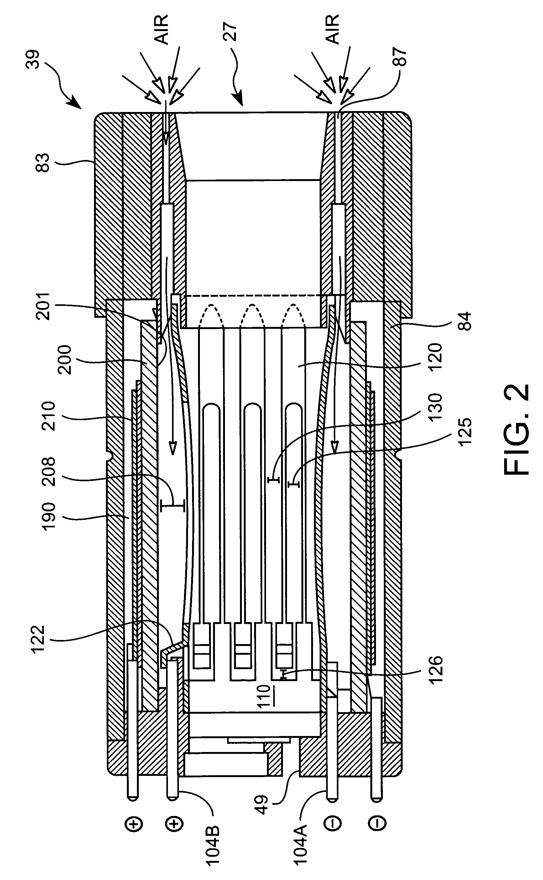
[0017]A heater fixture of an electrical smoking system having improved air flow is described below. Electrically heated cigarette smoking systems are described in greater detail in U.S. Pat. Nos. 5,388,594 and 5,878,752, which are hereby incorporated by reference in their entireties. The fixture used in the electrically heated cigarette smoking systems described in the above patents is shown in FIGS. 1 and 2 of the present application. A specially designed cigarette is adapted to be inserted in and removed from an orifice 27 at a front end of the heater fixture 39. The heater fixture 39 is preferably substantially cylindrical, and holds a cigarette in place relative to the electrically heated cigarette smoking system in which the heater fixture is supported. Electrical control circuitry can also be provided within the electrically heated cigarette smoking system for delivering a predetermined amount of energy from a power source to the cigarette heater elements 120, shown in FIG. 2....


PUM


Abstract

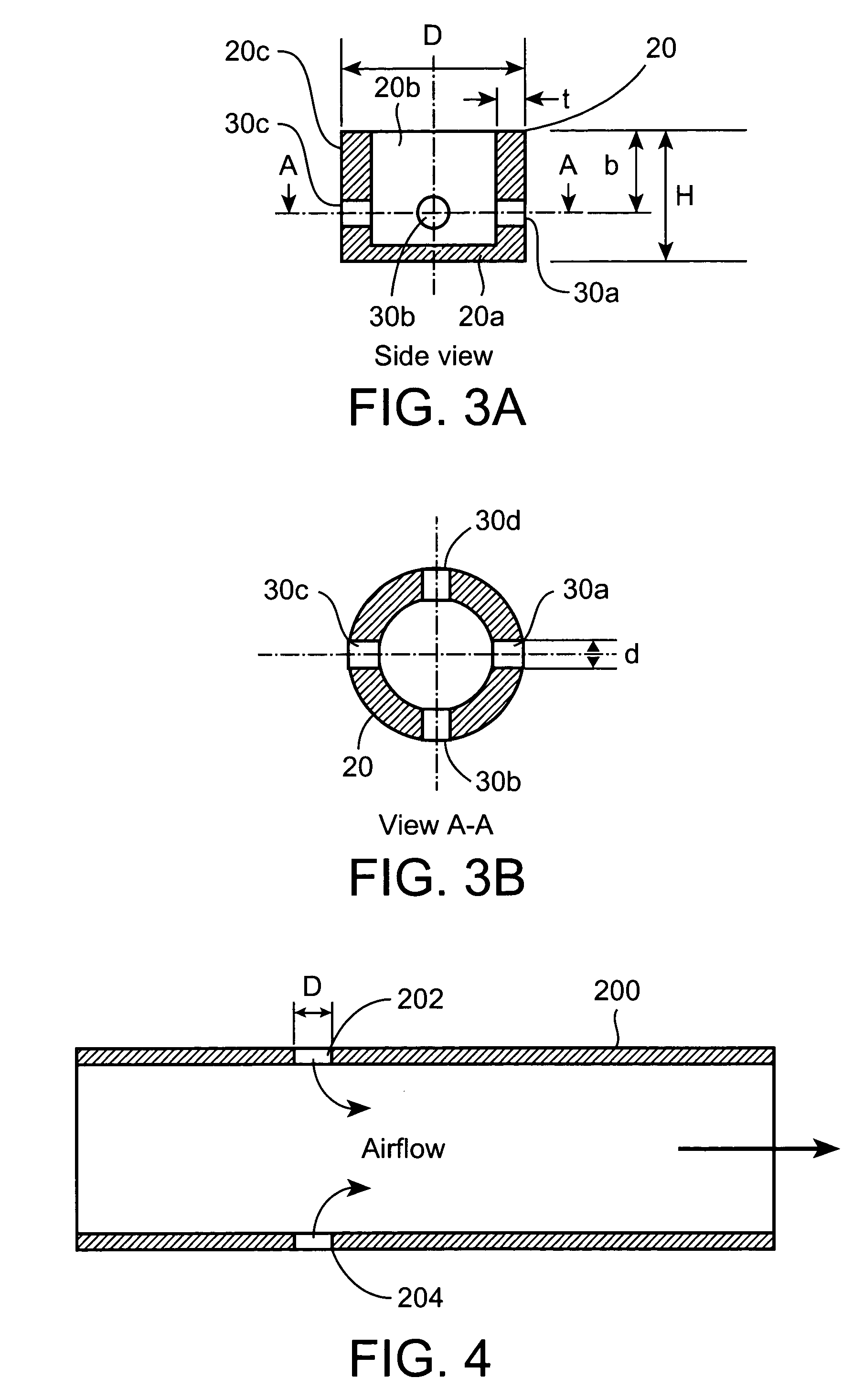
A heater fixture for use in an electrically heated cigarette smoking system having a source of electrical energy for heating a cigarette includes an inner wall or barrel having at least one opening through the inner wall extending from an outer peripheral surface to an inner surface of the inner wall, and at least one flow distributing element positioned within the at least one opening and extending inwardly from the inner surface. The flow distributing element or elements are provided with a plurality of openings that are in fluid communication with an interior of the heater.

Description

FIELD OF THE INVENTION[0001]The present invention relates to a heater for use in an electrically heated cigarette smoking system.BACKGROUND OF THE INVENTION[0002]Previously known conventional lit cigarettes deliver flavor and aroma to the user as a result of combustion of tobacco. A mass of combustible material, primarily tobacco, is oxidized as the result of applied heat with typical combustion temperatures in a conventional cigarette being in excess of 800 degrees Celsius during puffing.[0003]Lit-end cigarettes have some perceived drawbacks associated with them. Among them is the production of side stream smoke during smoldering between puffs, which may be objectionable to some non-smokers. Also, once lit, lit-end cigarettes must be fully consumed or discarded. Relighting a lit-end cigarette is possible but is usually an unattractive prospect for subjective reasons related to flavor, taste and odor.[0004]Electrical smoking systems including electrically powered lighters and specia...

Claims


Application Information

Patent Timeline
IPC IPC(8): A24F5/04A24F40/20A24F40/46A24F40/485
CPCA24F47/008A24F40/46A24F40/20A24F40/485A24F1/22A24F13/04A24F13/02A24F1/00
Inventor ROSTAMI, ALI A.WRENN, SUSAN E.
Owner PHILIP MORRIS USA INC
Learn More