
Pilot signals for synchronization and/or channel estimation

a pilot signal and channel estimation technology, applied in the field of communication systems, can solve the problems of difficult to achieve channel estimation for coherent detection, received signal suffers from frequency selective multipath fading, and is difficult to predict its behavior, so as to eliminate or prevent sidelobes, the effect of optimal autocorrelation results

Inactive Publication Date: 2006-01-17
LG ELECTRONICS INC
View PDF15 Cites 144 Cited by
  • Summary
  • Abstract
  • Description
  • Claims
  • Application Information

AI Technical Summary

Benefits of technology

[0040]An object of the present invention is to provide frame synchronization words resulting in optimal autocorrelation results.
[0041]A further object of the present invention is to eliminate or prevent sidelobes.
[0043]Another object of the present invention is to provide a synchronization word for at least one of rapid and accurate frame synchronization.
[0046]Still another object of the present invention is to provide good cross-correlation and autocorrelation simultaneously.

Problems solved by technology

It is rather difficult to predict its behavior.
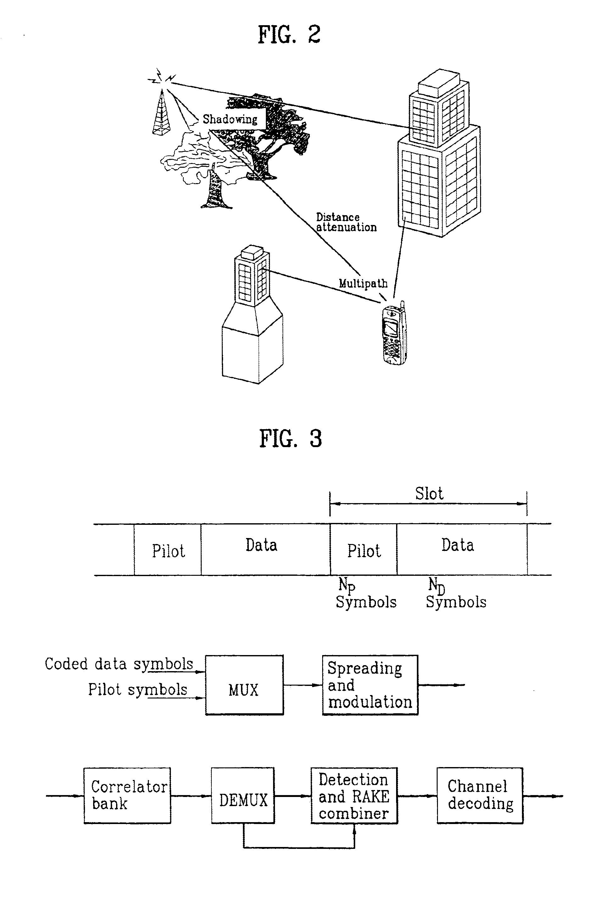
Due to the interference among many multipaths with different time delays, the received signal suffers from frequency selective multipath fading.
While coherent detection can be used to increase link capacity, under such fast fading, the channel estimation for coherent detection is generally very difficult to achieve.
Because of fading channels, it is hard to obtain a phase reference for the coherent detection of data modulated signal.
It has been noticed that common control channels are often problematic in the downlink when adaptive antennas are used.
Good autocorrelation properties are required for reliable initial synchronization, since large sidelobes of the autocorrelation function may lead to erroneous code synchronization decisions.
The autocorrelation and cross-correlation functions are connected in such a way that it is not possible to achieve good autocorrelation and cross-correlation values simultaneously.
However, the various pilot patterns recommended in the TS S1.11 v1.1.0 do not meet this requirement, both in the uplink and downlink.
However, the article does not provide how such sequences and autocorrelation can be used to achieve the above described optimal results, and the article does not provide sufficient disclosure that the sequences achieve or can achieve the lowest autocorrelation sidelobes.
As described above, the pilot patterns used as frame synchronization words or sequences do not achieve the optimal results.
Further, the background pilot patterns do not rapidly and accurately perform the frame synchronization.
Moreover, the above pilot patterns and frame synchronization sequences do not provide optimal cross-correlation and autocorrelation.
Additionally, neither the TS specification nor the article provides a solution of the use of the pilot patterns for slot-by-slot double check frame synchronization scheme, and neither discloses the use of the frame synchronization sequence for channel estimation.

Method used


Image

  • Pilot signals for synchronization and/or channel estimation
  • Pilot signals for synchronization and/or channel estimation
  • Pilot signals for synchronization and/or channel estimation

Examples


first embodiment

of Downlink DPCH, PCCPCH and SCCPH for STTD Diversity

[0206]FIG. 19A illustrates new pilot symbol patterns of Downlink DPCH for the diversity antenna using a space time block coding based transmit diversity (STTD). For the diversity pilot symbol pattern on downlink DPCH, STTD is applied to the shaded pilot symbols #1 and #3 for Npilot=8, and the shaded pilot symbols #1, #3, #5, and #7 for Npilot=16. The non-shaded pilot symbols #0 and #2 for Npilot=8, and non-shaded pilot symbols #0, #2, #4, and #6 for Npilot=16 are encoded to be orthogonal to the pilot symbol of FIG. 15A. However, the diversity pilot pattern for downlink DPCH with Npilot=4 are STTD encoded since STTD encoding requires two symbols. FIG. 19B illustrates the mapping relationship between the 8 words C1-C8 of FIG. 12A and shaded pilot symbol patterns of FIG. 19A.

[0207]FIG. 19C illustrates the new diversity antenna pilot symbol pattern for PCCPCH. The pilot symbols of FIG. 19C are encoded to be orthogonal to the pilot sym...


PUM


Abstract

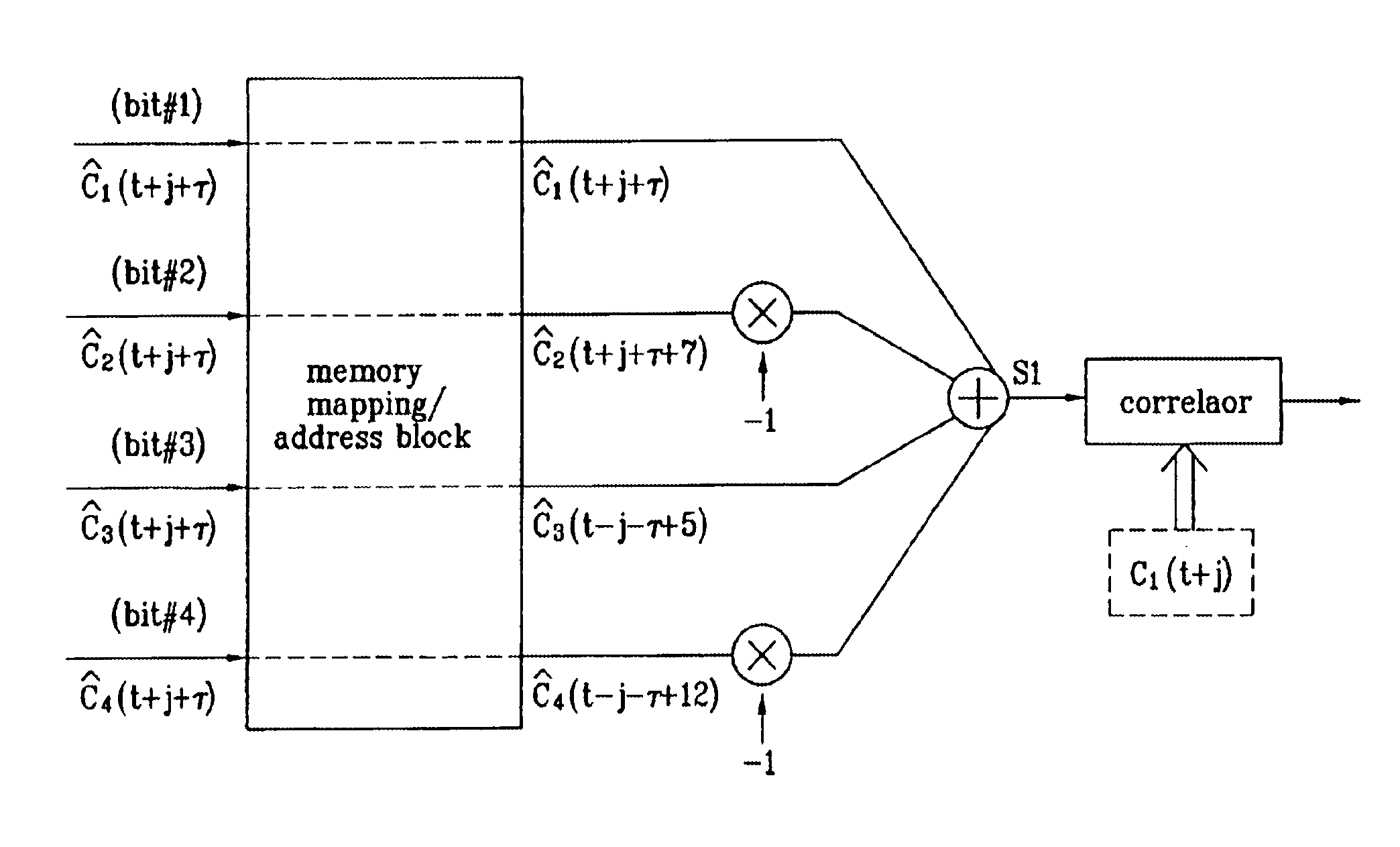
The frame words of the preferred embodiment are especially suitable for frame synchronization and / or channel estimation. By adding the autocorrelation and cross-correlation functions of frame words, double maximum values equal in magnitude and opposite polarity at zero and middle shifts are obtained. This property can be used to slot-by-slot, double-check frame synchronization timing, single frame synchronization and / or channel estimation and allows reduction of the synchronization search time. Further, the present invention allows a simpler construction of a correlator circuit for a receiver. A frame synchronization apparatus and method using an optimal pilot pattern is used in a wide band code division multiple Access (W-CDMA) next generation mobile communication system. This method includes the steps of storing column sequences demodulated and inputted by slots, in a frame unit, in detecting frame synchronization for upward and downward link channels; converting the stored column sequences according to a pattern characteristic related to each sequence by using the pattern characteristic obtained from the relation between the column sequences; adding the converted column sequences by slots; and performing a correlation process of the added result to a previously designated code column.

Description

[0001]This application claims the benefit of U.S. Provisional Application No. 60 / 136,763 filed May 28, 1999, and this application is also a continuation-in-part of application Ser. No. 09 / 373,703 U.S. Pat. No. 6,791,960 and application Ser. No. 09 / 376,373 U.S. Pat. No. 6,721,299 filed Aug. 13, 1999 and Aug. 18, 1999, respectively, and application Ser. No. 09 / 525,444 U.S. Pat. No. 6,804,264, application Ser. Nos. 09 / 525,446, and 09 / 525,448, all filed Mar. 14, 2000, whose entire disclosure is incorporated herein by reference therein.BACKGROUND OF THE INVENTION[0002]1. Field of the Invention[0003]The present invention relates to communication systems, and more particularly, wireless communication systems, preferably, wide band code division multiple access (W-CDMA) communication systems.[0004]2. Background of the Related Art[0005]The use of code division multiple access (CDMA) modulation techniques is one of several techniques for facilitating communications in which a large number of ...

Claims


Application Information

Patent Timeline
IPC IPC(8): H04B7/216H04J3/06
CPCH04W56/0085H04B7/264H04B2201/70701
Inventor SONG, YOUNG-JOON
Owner LG ELECTRONICS INC
Learn More