Wireless communication system and wireless station
a wireless communication and wireless technology, applied in the field of wireless communication system and wireless station, can solve the problem that the simultaneous communication of multiple stations through the same channel cannot be efficiently performed in space division multiple communication, and achieve the effect of facilitating simultaneous communication between multiple stations
- Summary
- Abstract
- Description
- Claims
- Application Information
AI Technical Summary
Benefits of technology
Problems solved by technology
Method used
Image
Examples
second embodiment
(Second Embodiment)
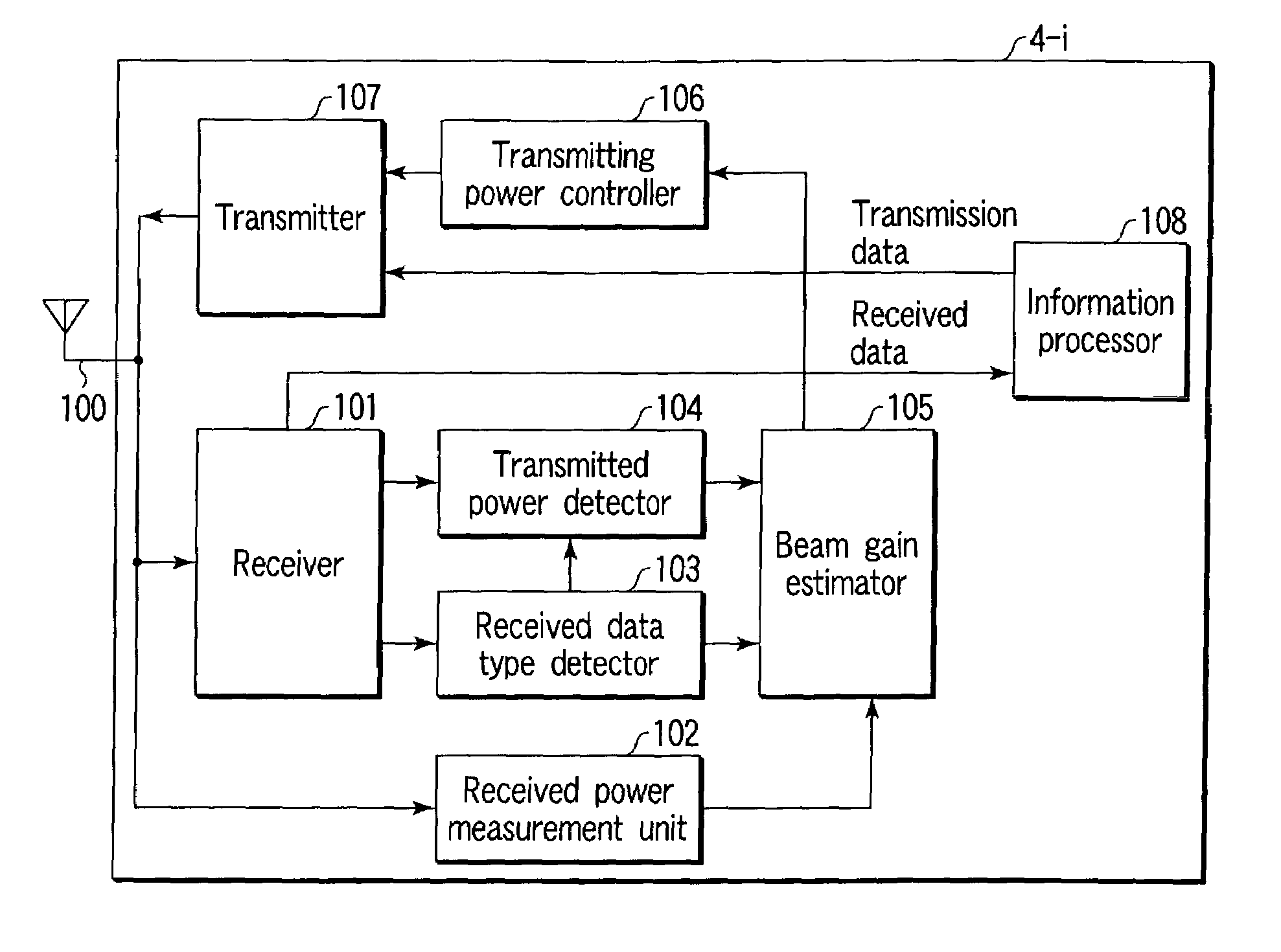
[0119]In the first embodiment described above, the station (STA) 4-i performs transmitter power control. In the second embodiment, this station (STA) 4-i controls a carrier sense level.
[0120]This second embodiment is basically the same as the first embodiment. That is, the station (STA) 4-i checks whether an access point 1 is performing directional beam control, from received power of broadcast frame transmitted by the access point 1 and its transmitted power information, and from received power of unicast frame transmitted by the access point 1 and its transmitted power information (if it is determined that the access point 1 is performing directional beam control, the station (STA) 4-i further checks whether the directivity is narrowed enough at the access point 1 to perform SDMA). If it is determined that the access point 1 is performing directional beam control (such that the directivity is narrowed enough to perform SDMA), the station (STA) 4-i raises its car...
third embodiment
(Third Embodiment)
[0131]IEEE802.11 defines an access control method called RTS (Request To Send) / CTS (Clear To Send). This method ensures the transmission right by using the MAC control frames. This RTS / CTS control uses an RTS frame and a CTS frame and their frame formats are different from the one for a data frame shown in FIG. 5A. Both RTS and CTS frames consists of only MAC header and FCS. The MAC header of RTS consists of frame control field F1, duration field, RA, and TA. As for CTS, the MAC header consists of frame control field F1, duration field, and RA. Whether the RTS frame or CTS frame is used can be checked from the type field F1a and the subtype field F1b in the frame control field F1 of the MAC header.
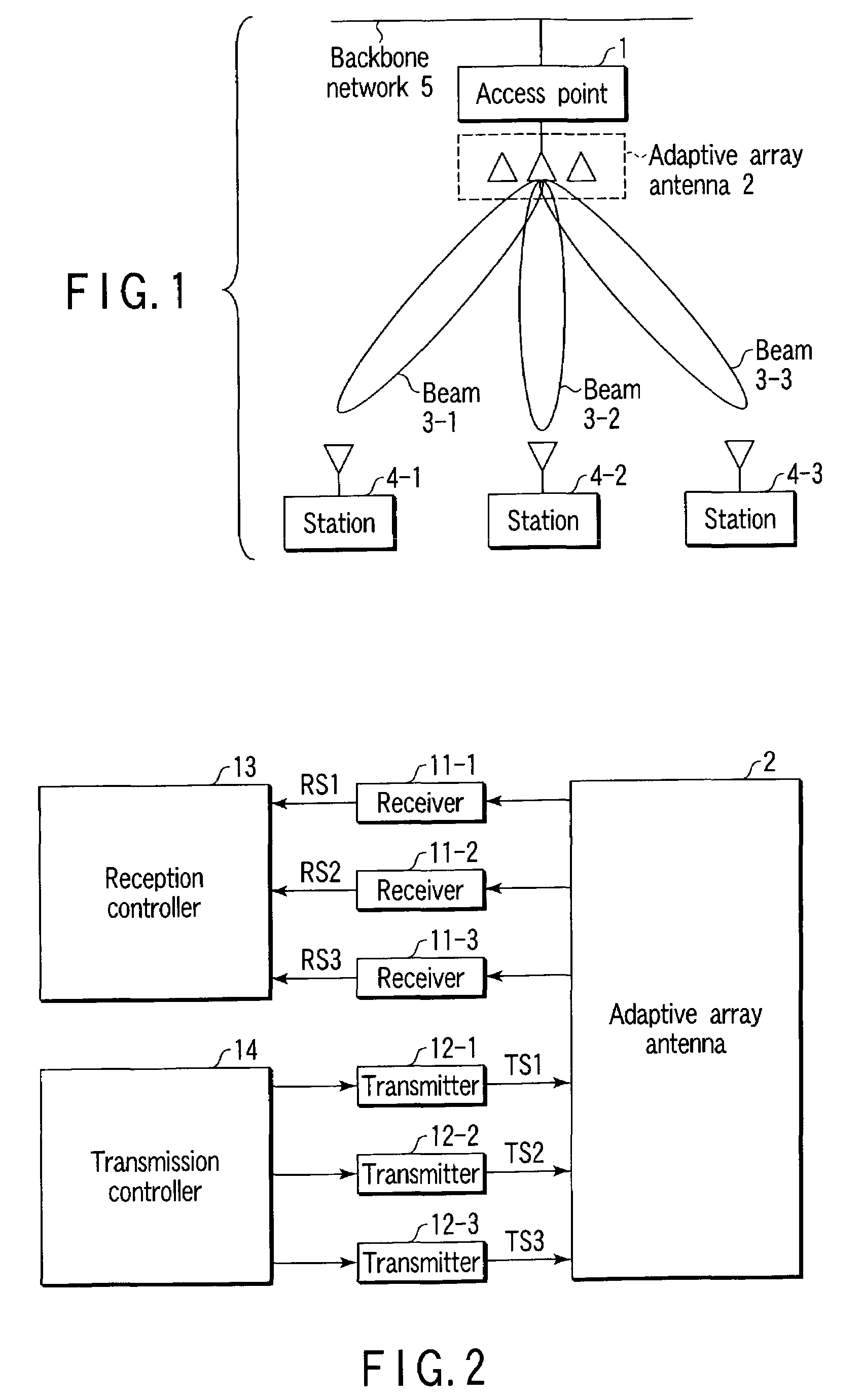
[0132]This RTS / CTS control method is also applicable to the wireless communication system shown in FIG. 1. In this case, when receiving an RTS frame from a station (STA) 4-i, a wireless access point 1 transmits a CTS frame as a response to the station (STA) 4-i by using a...
PUM
 Abstract
Description
Claims
Application Information
 - R&D
- Intellectual Property
- Life Sciences
- Materials
- Tech Scout
- Unparalleled Data Quality
- Higher Quality Content
- 60% Fewer Hallucinations
Browse by: Latest US Patents, China's latest patents, Technical Efficacy Thesaurus, Application Domain, Technology Topic, Popular Technical Reports.
© 2025 PatSnap. All rights reserved.Legal|Privacy policy|Modern Slavery Act Transparency Statement|Sitemap|About US| Contact US: help@patsnap.com


