
Image detector method and apparatus including plural detector regions and image illuminators

a detector and image technology, applied in the field of digital cameras, can solve the problems of reducing the processing time and data storage capacity of the process of irradiating glare spots in this manner, and the severe limitations of the digital camera employed in this manner as a document image capture device,

Inactive Publication Date: 2005-12-13
LIBRE HLDG
View PDF9 Cites 54 Cited by
  • Summary
  • Abstract
  • Description
  • Claims
  • Application Information

AI Technical Summary

Benefits of technology

The system effectively eliminates glare spots from document images while reducing the need for double data capture and processing, resulting in more efficient image acquisition and storage.

Problems solved by technology

However, a digital camera employed in this manner as a document image capture device has severe limitations due to the phenomena of specular reflections.
However, obtaining two complete document images containing the two glare spots, requires the camera to receive, process and store twice as much information as would be required if only one image was obtained.
This process for irradiating glare spots in this manner is therefore a relatively expensive process in terms of data storage capacity and processing time.

Method used


Image

  • Image detector method and apparatus including plural detector regions and image illuminators
  • Image detector method and apparatus including plural detector regions and image illuminators
  • Image detector method and apparatus including plural detector regions and image illuminators

Examples


Embodiment Construction

[0073]There will now be described by way of example the best mode contemplated by the inventors for carrying out the invention. In the following description numerous specific details are set forth in order to provide a thorough understanding of the present invention. It will be apparent however, to one skilled in the art, that the present invention may be practiced without limitation to these specific details. In other instances, well known methods and structures have not been described in detail so as not to unnecessarily obscure the present invention.

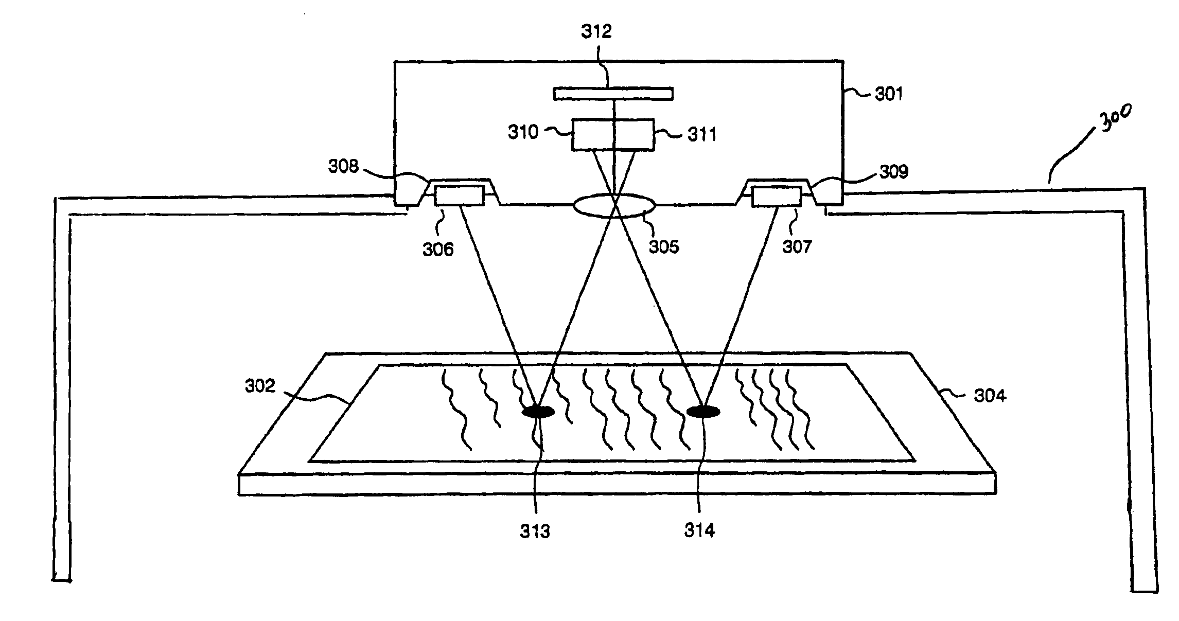
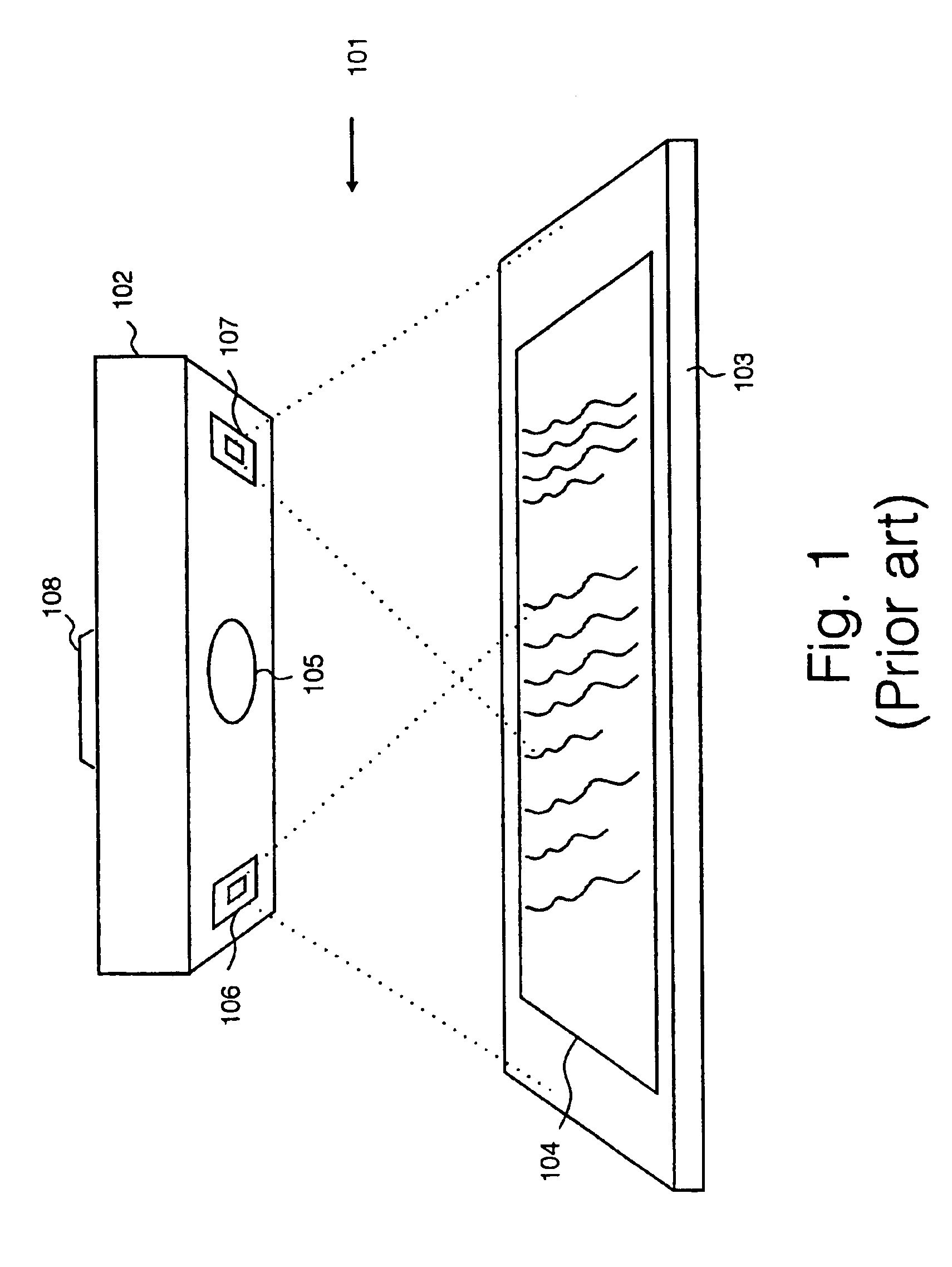
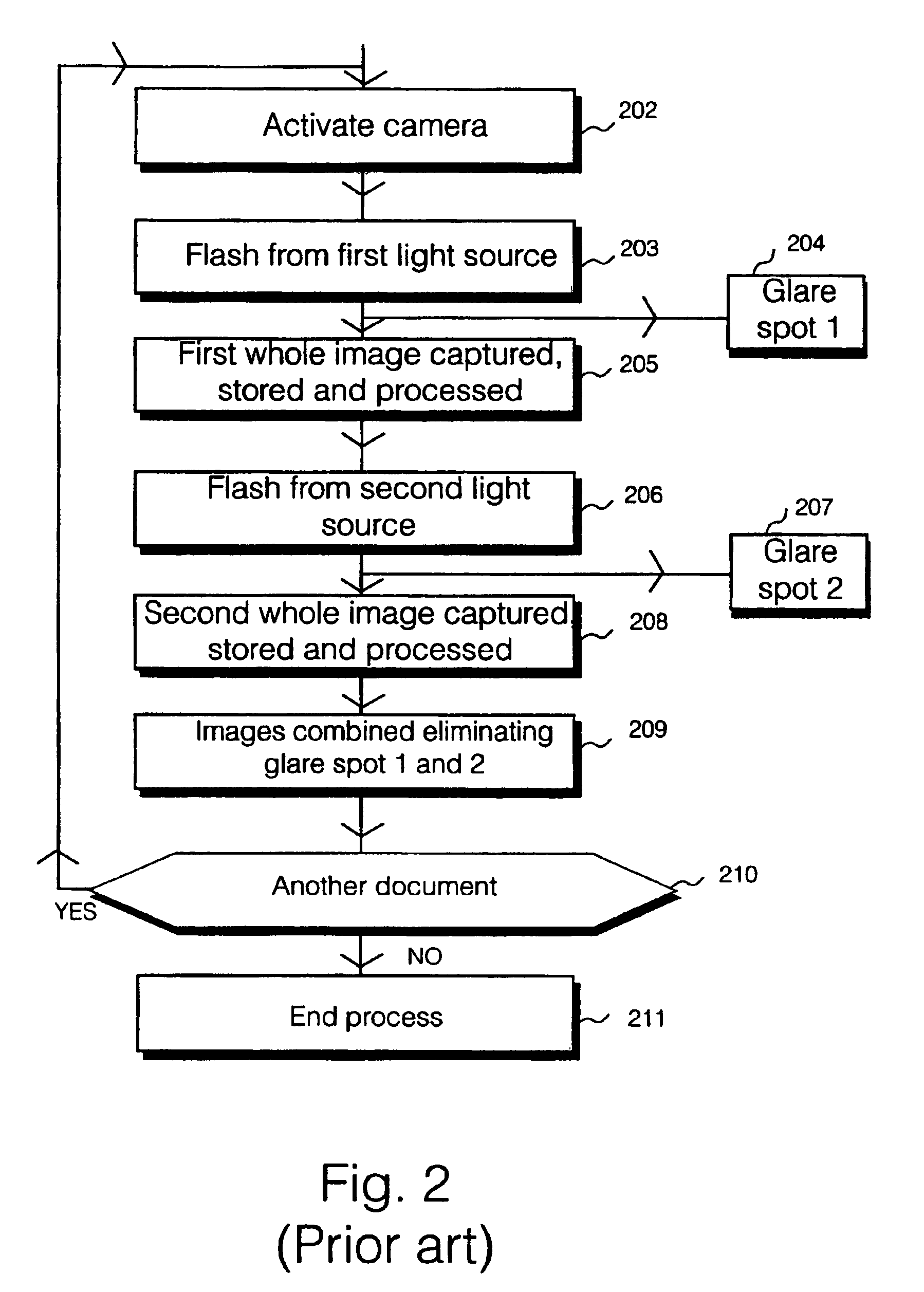
[0074]FIG. 1 illustrates a prior art photography system 101 including digital camera positioned vertically above a document 104 resting on a flat surface 103. The digital camera 102, comprises a lens 105 located substantially central on the lower face of the digital camera 102. Also present on the lower surface of the digital camera 102, placed diametrically opposite on a circle with the lens 105 at the center of the circle, is a firs...


PUM


Abstract

A digital camera has first and second light sources for sequentially illuminating a document from two different directions in response to the camera being activated. The camera has first and second sensor portions. Only the first and second sensor portions respectively respond to images reflected from the document in response to the first and second sources illuminating the document. Images detected by the first and second sensor portions are combined to remove specular reflection from the document image. In a second embodiment, the camera has three sensor portions.

Description

FIELD OF THE INVENTION[0001]The present invention relates to digital camera, and particularly although not exclusively, to a digital camera configured to obtain an image of a document.BACKGROUND TO THE INVENTION[0002]Digital cameras are known in the prior art and in their simplest form comprise a light, typically a flash light, a sensor containing image sensitive nodes and image storage nodes, a lens or series of lenses and a memory bank. The digital camera is known to be employed as an image capture device for capturing images of documents, and in operation is held in a fixed position over a document. The flash light is then triggered thus illuminating the document. The lens serves to focus the image onto the light sensitive nodes and the image is transferred to light storage nodes within the sensor. The final image is read out to a suitable memory bank where it is stored indefinitely awaiting a final process, for example, downloading onto a computer hard-drive or floppy disk.[0003...

Claims


Application Information

Patent Timeline
Patent Type & Authority Patents(United States)
IPC IPC(8): H04N1/028H04N1/195H04N1/21H04N1/40
CPCH04N1/02815H04N1/0282H04N1/195H04N1/2104H04N1/40056H04N2101/00H04N2201/0426H04N2201/0436
Inventor SLATTER, DAVID NEIL
Owner LIBRE HLDG
Learn More