
Air filtration system including a helmet assembly

a technology of which is applied in the direction of hats, breathing protection, protective garments, etc., can solve the problems of deficient air filtration system and helmet assembly of this patent, deficient in air distribution that is not completely distributed, and deficient in intake grid, so as to maximize the effective intake area and minimize the effect of strain and fatigue in the user

Inactive Publication Date: 2005-12-13
STRYKER CORP
View PDF92 Cites 85 Cited by
  • Summary
  • Abstract
  • Description
  • Claims
  • Application Information

AI Technical Summary

Benefits of technology

The system provides balanced air distribution, reduces user strain, assists in self-gowning without compromising sterility, and maintains constant air flow volume, enhancing comfort and efficiency during surgical procedures.

Problems solved by technology

Conventional air filtration systems and helmet assemblies are deficient for one reason or another.
The air filtration system and helmet assembly of this patent are deficient in that air is not distributed completely about the head of the user.
Further, the intake grid is deficient in that the grid does not extend between a front and rear section of the helmet assembly to maximize an effective intake area for the filter medium.
The air filtration system and helmet assembly of this patent is deficient in that they are overly heavy due to the additional fan required to exhaust air.
Furthermore, the exhaust fan creates excessive strain, and therefore fatigue, in the neck of the user because the exhaust fan is spaced away from the neck of the user.
The conventional air filtration system and helmet assembly disclosed in U.S. Pat. No. 5,711,033 to Green et al. is also deficient.
The air filtration and helmet assembly of this patent is deficient because the intake fan and scroll housing are spaced away from the neck of the user.
Further, the scroll housing in this patent includes only one air outlet to distribute air about the head of the user resulting in less balanced air flow throughout the helmet assembly.
Additional drawbacks of such an air filtration system and helmet assembly including only one air outlet from the scroll housing are excessive fog build-up and poorer heat dissipation in the helmet assembly.
Other conventional air filtration systems and helmet assemblies are also deficient for the following reasons.
First, these conventional air filtration systems and helmet assemblies do not assist a single user in self-gowning as the surgeon maintains sterility.
That is, these air filtration systems and helmet assemblies do not include a positioning and supporting system that automatically centers a face shield over the helmet assembly and that supports an entire weight of the gown and face shield.
Furthermore, randomly-placed hook-and-loop fasteners do not automatically center the face shield and do not support the entire weight of the gown and the face shield as the surgeon self-gowns.
This is time consuming and burdensome.
Secondly, it is generally understood that the amount of air flowing into the helmet assembly is critical for anti-fogging and heat control purposes.
However, the air filtration systems and helmet assemblies of the prior art do not assist the surgeon in recognizing the amount, or volume, of air flowing into the helmet assembly.
That is, these air filtration systems and helmet assemblies do not provide audible indication to the surgeon of the volume of air flowing into the helmet assembly during any particular surgical procedure.
The prior art air filtration systems and helmet assemblies do not incorporate a strap flexibly connected to the front section of the helmet assembly such that the strap is pulled from the front section of the helmet assembly and the weight of any fans is maintained over the user's neck when the helmet assembly is adjusted to fit various sized heads.

Method used


Image

  • Air filtration system including a helmet assembly
  • Air filtration system including a helmet assembly
  • Air filtration system including a helmet assembly

Examples


Embodiment Construction

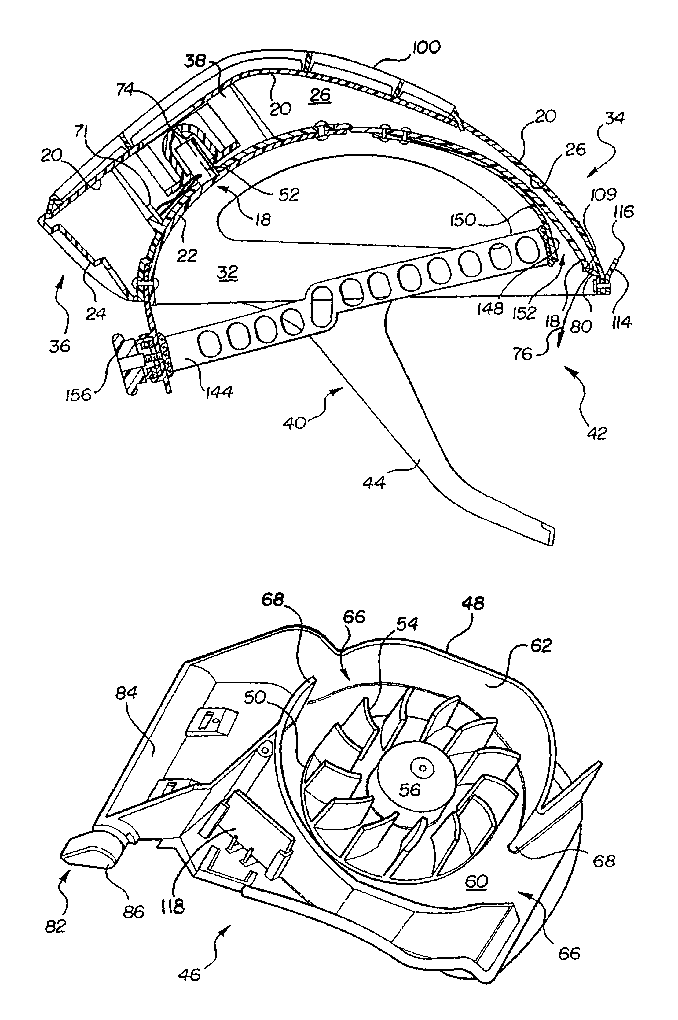
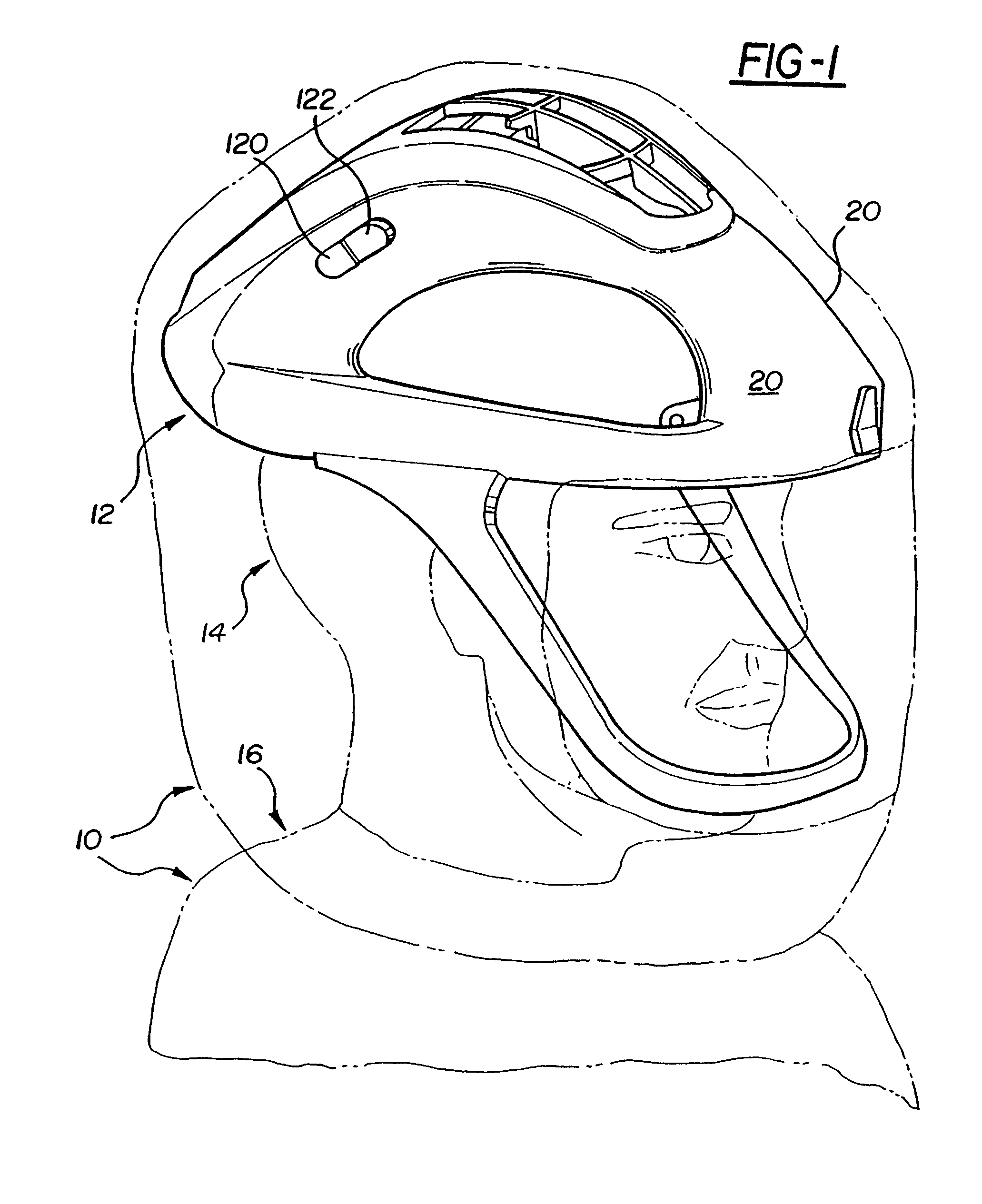
[0038]Referring to the Figures, wherein like numerals indicate like or corresponding parts throughout the several views, an air filtration system and helmet assembly are generally disclosed at 10 and 12, respectively. Referring to FIG. 1, the air filtration system 10 filters air between a head 14 and body 16 of a user and an environment external to the user and includes the helmet assembly 12 mounted to the head 14 of a user. The helmet assembly 12 distributes air about the head 14 of the user as will be described below. More specifically, the helmet assembly 12 distributes air toward both a front of the head 14, i.e., the face, of the user, and a back of the head 14, i.e., the neck, of the user.

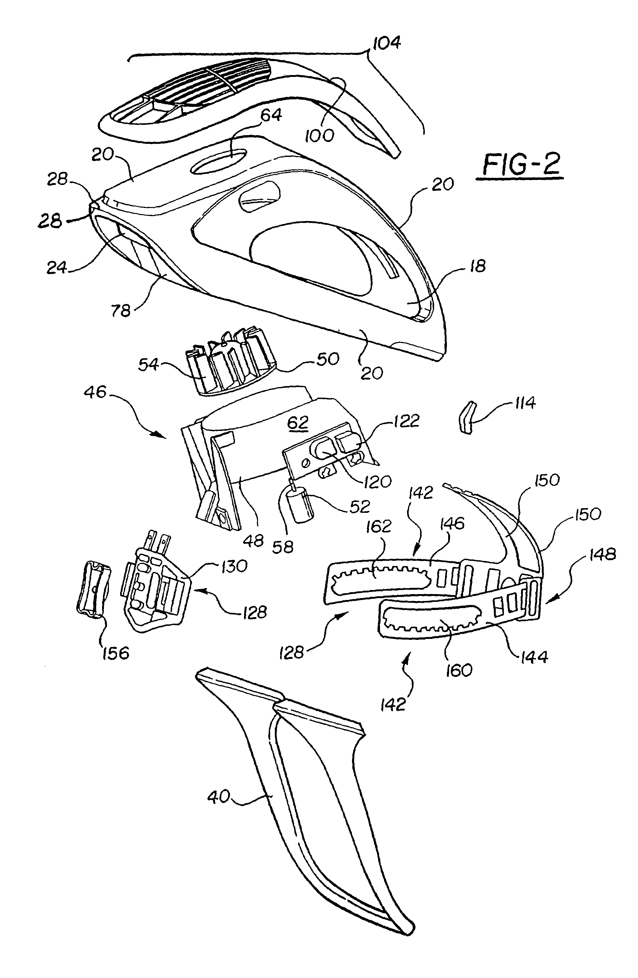
[0039]Referring now to FIGS. 2 and 3, the helmet assembly 12 includes an inner structural shell 18 and an outer structural shell 20. The inner shell 18 includes a cover surface 22 and a rear facing 24 which extend to the outer shell 20. The cover surface 22 and rear facing 24 will be discuss...


PUM


Abstract

An air filtration system and a helmet for use in the air filtration system are disclosed and utilized to filter air between a head and body of a user and an external environment. The air filtration system and helmet include inner and outer shells that define an air flow channel for channeling air about the user. A fan module is mounted between the inner and outer shells and a scroll housing is mounted adjacent the fan module. The scroll housing includes an air inlet for drawing air into the air filtration system and helmet, and at least one air outlet to distribute air flow to the air flow channel. The helmet includes air exits at front and rear sections that are in fluid communication with the air flow channel and the air outlet or outlets. The air filtration system includes a gown operating as a filter for filtering the air.

Description

RELATED APPLICATIONS[0001]This patent application is a divisional of application Ser. No. 10 / 625,309, filed Jul. 23 2003, which is a continuation of application Ser. No. 10 / 188,656, filed Jul. 2, 2002, now U.S. Pat. No. 6,622,311, which is a continuation of application Ser. No. 09 / 764,697, filed Jan. 18, 2001, now U.S. Pat. No. 6,481,019, which claims priority to and all advantages of U.S. Provisional Patent Application No. 60 / 176,958 which was filed on Jan. 18, 2000.BACKGROUND OF THE INVENTION[0002]1) Technical Field[0003]The subject invention generally relates to an air filtration system for filtering air between a head and body of a user and an environment external to the user. The air filtration system is utilized in the medical profession during surgical procedures. The subject invention more specifically relates to a helmet assembly and gown for use in the air filtration system.[0004]2) Description of the Prior Art[0005]Air filtration systems and helmet assemblies utilized in ...

Claims


Application Information

Patent Timeline
Patent Type & Authority Patents(United States)
IPC IPC(8): A42B3/28A41D13/11A42B3/18A62B18/04
CPCA41D13/11A41D13/1153A42B3/286A62B18/045
Inventor DIAZ, LUIS A.HENNIGES, BRUCE D.WASSERMAN, MARK A.SMIT, KAREN L.
Owner STRYKER CORP
Learn More