
Line driver for asymmetric digital subscriber line system

a technology of asymmetric digital subscriber lines and driver systems, applied in the field of digital subscriber lines (dsl) technologies, can solve the problems of reducing the amount of receive signals developed across these resistors, wasting one-half of wasting the power provided by the line driver amplifiers

Inactive Publication Date: 2005-11-29
AVAGO TECH INT SALES PTE LTD
View PDF6 Cites 20 Cited by
  • Summary
  • Abstract
  • Description
  • Claims
  • Application Information

AI Technical Summary

Problems solved by technology

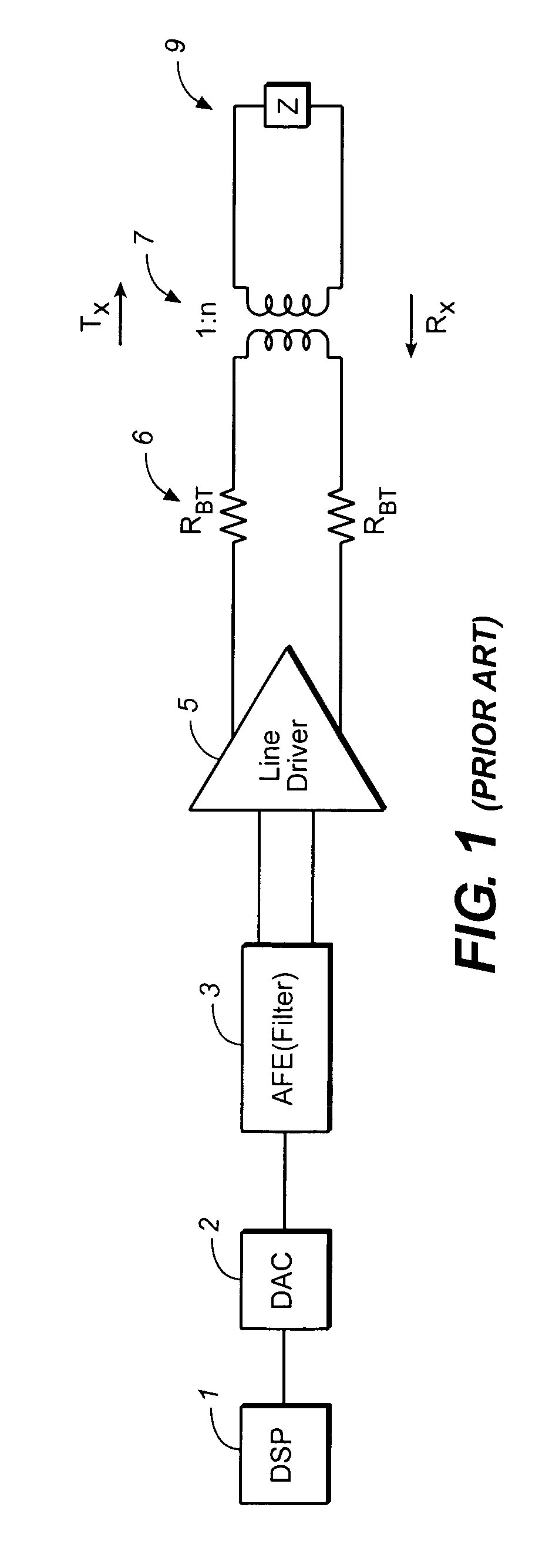
Although the back-termination resistors are necessary to prevent undesirable reflection of the receive signal, they waste one-half of the power provided by the line driver amplifiers.
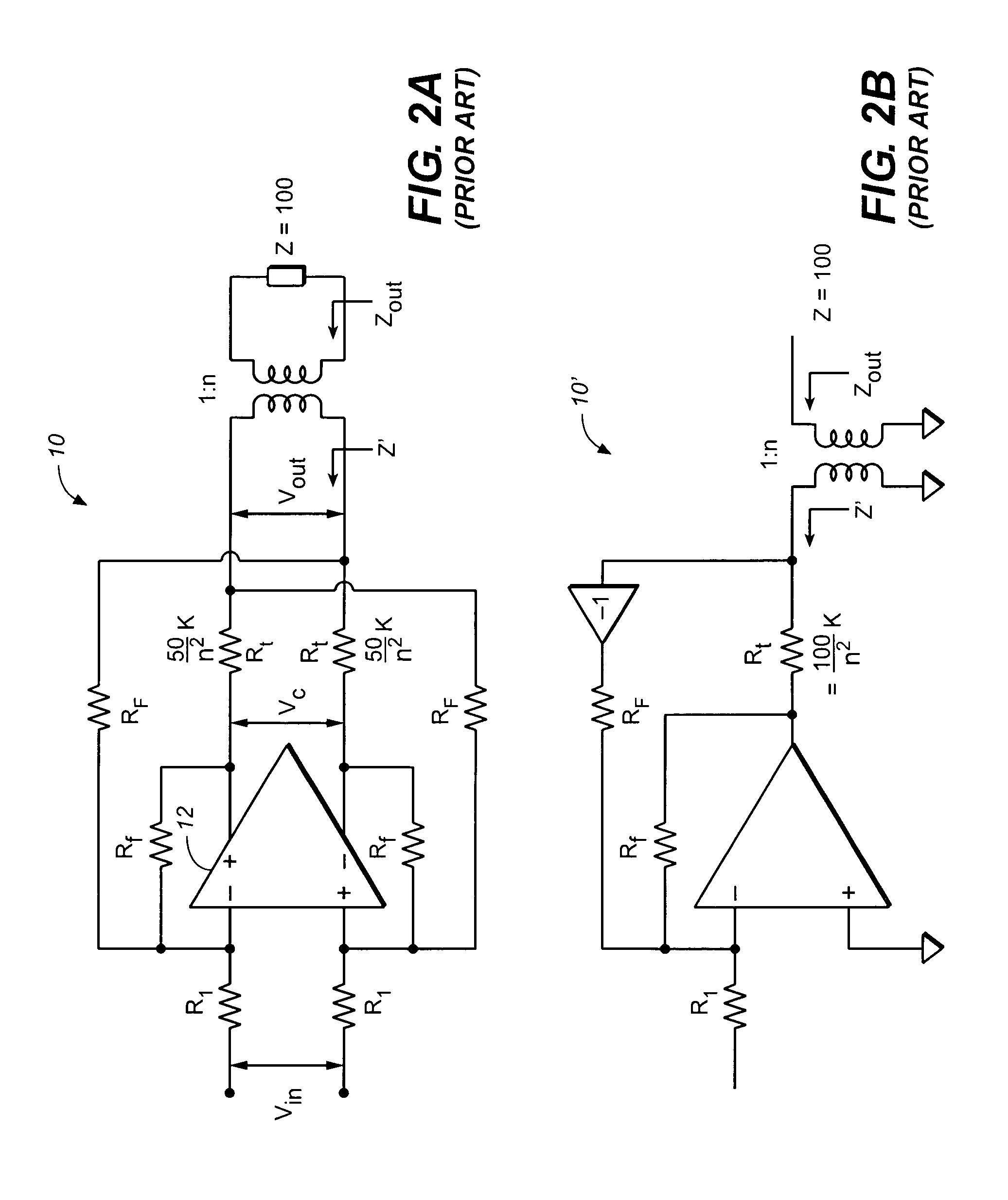
However, simply reducing a termination resistance causes mistermination of the receive signal as well as reducing the amount of the receive signal developed across these resistors to be sensed by a receive circuit.
Because the Rauch filter is inherently frequency dependent, it is unknown to those of ordinary skill in the art how any additional components affect the required filter characteristic, or whether such additional components operate as intended.

Method used


Image

  • Line driver for asymmetric digital subscriber line system
  • Line driver for asymmetric digital subscriber line system
  • Line driver for asymmetric digital subscriber line system

Examples


Embodiment Construction

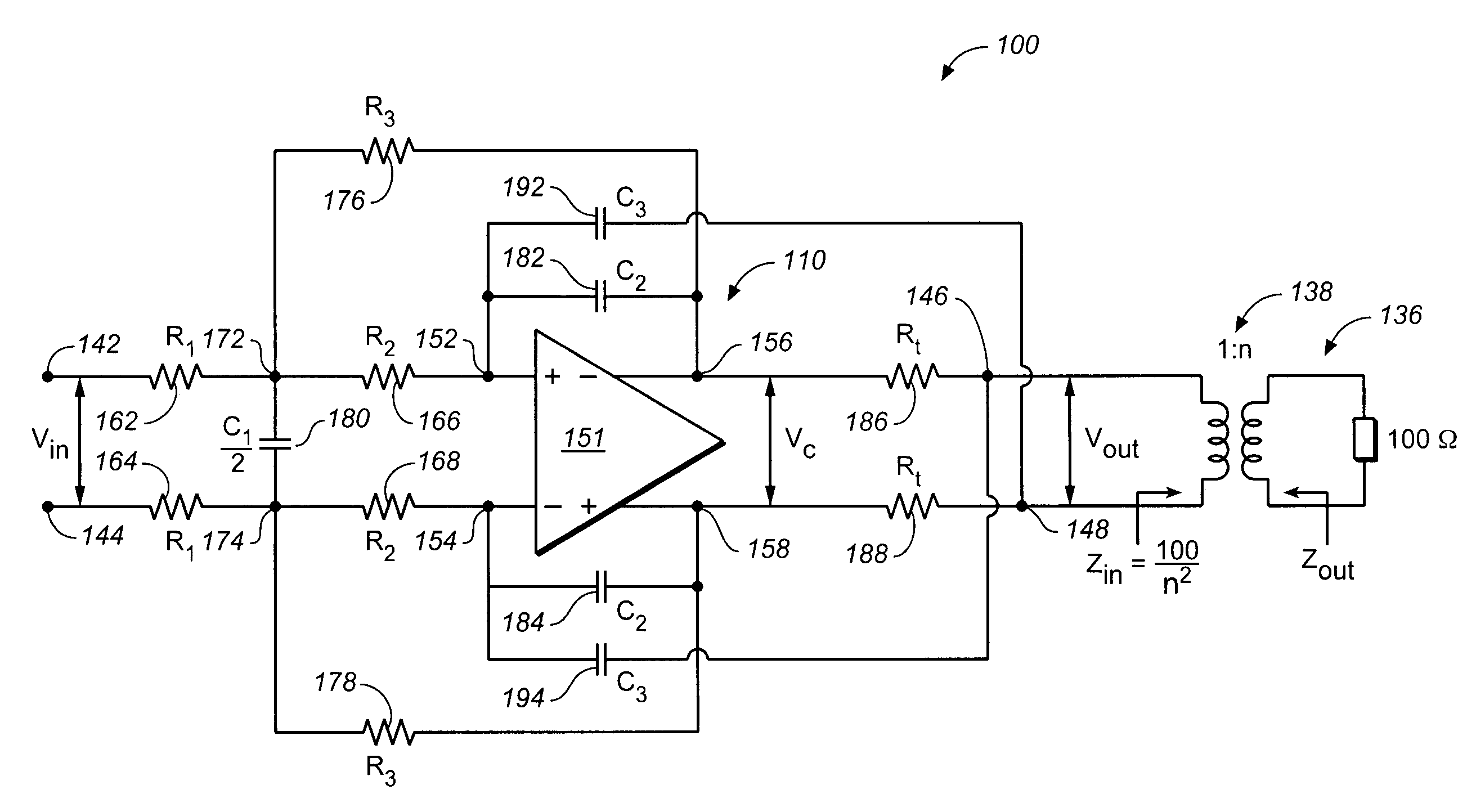
[0031]Embodiments of the present invention are described herein in the context of a line driver for ADSL system. Those of ordinary skill in the art will realize that the following detailed description of the present invention is illustrative only and is not intended to be in any way limiting. Other embodiments of the present invention will readily suggest themselves to such skilled persons having the benefit of this disclosure. Reference will now be made in detail to implementations of the present invention as illustrated in the accompanying drawings. The same reference indicators will be used throughout the drawings and the following detailed description to refer to the same or like parts.

[0032]In the interest of clarity, not all of the routine features of the implementations described herein are shown and described. It will, of course, be appreciated that in the development of any such actual implementation, numerous implementation-specific decisions must be made in order to achie...


PUM


Abstract

A line driver couples a data transceiver to a transmission line having a load impedance Z via a transformer with a turns ratio of 1:n, the data transceiver transmitting signals in a first frequency range and receiving signals in a second frequency range different from the first frequency range. The line driver includes an input port for receiving an input signal voltage, an output port for supplying an output signal voltage to the transformer, and a differential amplifier having a low pass filter for amplifying the input signal voltage and outputting an amplified signal voltage. The line driver further includes termination resistors having a resistance Rt, where Rt=Z2⁢n2×k(0<k≤1),and a positive feedback path for coupling the output signal voltage from the output port to an appropriate node of the differential amplifier so that a synthesized output impedance substantially matches the load impedance Z over the second frequency range.

Description

FIELD OF THE INVENTION[0001]The present invention relates to digital subscriber line (DSL) technologies. More particularly, the present invention relates to a line driver for an asymmetrical digital subscriber line (ADSL) system.BACKGROUND OF THE INVENTION[0002]DSL and ADSL systems use a technique called discrete multitone (DMT) for transmitting data. With DMT, a frequency band up to 1.2 MHz is split up into 256 tones (also referred to as subcarriers or subchannels) each spaced 4.3125 kHz apart. In a DSL / ADSL application, the tones are allocated for use depending on the direction of communication between a central office (CO) and a remote terminal (RT) or customer premises equipment (CPE).[0003]Communication from a CO to a RT / CPE (such as an end user's PC modem) is referred to as “downstream.” The direction of communication from a RT / CPE to the CO is called “upstream.” A higher and wider frequency range, for example, 176 kHz to 1.1 MHz, is allocated to the downstream communication, ...

Claims


Application Information

Patent Timeline
IPC IPC(8): H04B3/00H04L25/02
CPCH04L25/0278H04L25/0266
Inventor BICAKCI, ARACONROY, CORMAC S.
Owner AVAGO TECH INT SALES PTE LTD
Learn More