Methods for maintaining laser performance at extreme temperatures

a technology of extreme temperature and laser performance, applied in the direction of optical radiation measurement, semiconductor lasers, instruments, etc., can solve the problem of inaccurate temperature compensation scheme using thermistors

Inactive Publication Date: 2005-11-22
II VI DELAWARE INC
View PDF3 Cites 34 Cited by
  • Summary
  • Abstract
  • Description
  • Claims
  • Application Information

AI Technical Summary

Problems solved by technology

Under high-volume manufacturing conditions, however, the temperature compensation scheme using thermistors is inaccurate due to variations in thermistor characteristics and laser characteristics.

Method used


Image

  • Methods for maintaining laser performance at extreme temperatures
  • Methods for maintaining laser performance at extreme temperatures
  • Methods for maintaining laser performance at extreme temperatures

Examples


Embodiment Construction

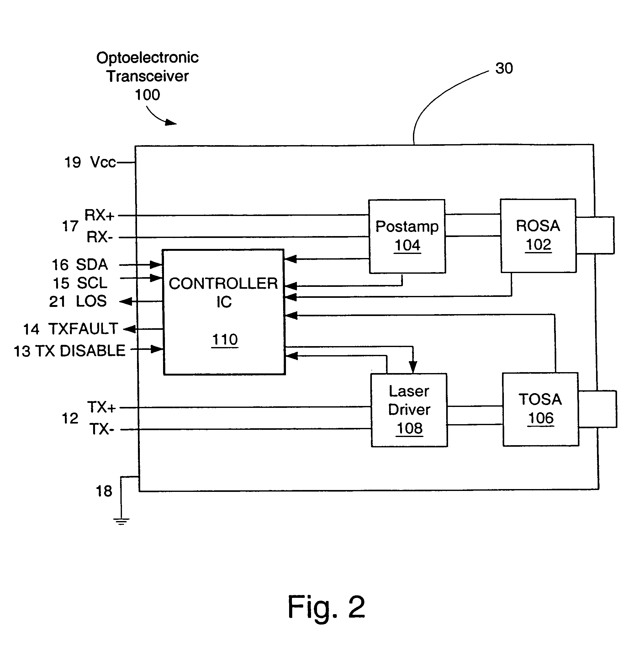
[0007]In general, exemplary embodiments of the invention are concerned with methods for calibrating optical emitters, such as lasers and laser diodes for example, in such a way that the optical emitters can be effectively employed in extreme operating conditions. In one exemplary implementation, the calibration method is employed in connection with an optical transceiver that includes an optical transmitter. Initially, a range of temperatures is defined that is bounded by a low end temperature and a high end temperature, where the low end temperature is less than the high end temperature. At a first temperature, within the predefined range, a first bias current to the optical transmitter is adjusted until the optical transmitter generates an optical signal at a first predefined power level. Next, at a second temperature outside the predefined range, a second bias current to the optical transmitter is adjusted until the optical transmitter generates an optical signal at a second pred...


PUM


Abstract

This disclosure concerns methods for calibrating optical emitters. For example, one calibration method is employed in connection with an optical transceiver that includes a laser. A range of temperatures is defined that includes low end and high end temperatures. At a first temperature, within the range, a first bias current to the laser is adjusted until the laser generates an optical signal at a first predefined power level. At a second temperature outside the range, a second bias current to the laser is adjusted until the laser generates an optical signal at a second predefined power level. If the second temperature is greater than the high end temperature, the second predefined power level is defined as less than the first predefined power level, and if the second temperature is less than the low end temperature, the second predefined power level is defined as greater than the first predefined power level.

Description

RELATED APPLICATIONS[0001]This application is a division, and claims the benefit, of U.S. patent application Ser. No. 10 / 285,369, entitled MAINTAINING DESIRABLE PERFORMANCE OF OPTICAL EMITTERS AT EXTREME TEMPERATURES, filed Oct. 31, 2002, which, in turn, claims the benefit of U.S. Provisional Patent Application Ser. No. 60 / 357,070, entitled METHOD OF MAINTAINING DESIRABLE OPTICAL PERFORMANCE OF LASER EMITTERS OVER TEMPERATURE VARIATIONS, filed Feb. 12, 2002. All of the aforementioned patent applications are incorporated herein in their respective entireties by this reference.BRIEF DESCRIPTION OF THE INVENTION[0002]The present invention relates generally to the field of fiber optic transceivers and particularly to circuits used within the transceivers to maintain desirable optical performance of optical emitters over temperature variations.BACKGROUND OF THE INVENTION[0003]FIG. 1 shows a schematic representation of the essential features of a typical prior-art fiber optic transceiver....

Claims


Application Information

Patent Timeline
Patent Type & Authority Patents(United States)
IPC IPC(8): H01S5/00H01S5/068H01S5/40
CPCH01S5/06804H01S5/06825H01S5/40
Inventor CHIENG, YEW-TAIHSIEH, JOHNLIGHT, GRETA L.
Owner II VI DELAWARE INC
Why Eureka
Try Eureka