
Measurement and marking device

a marking device and measurement technology, applied in the field of measuring systems, can solve the problems of inaccurate recording of the measurement by the user, the number of errors that occur in the typical measurement transfer process, and the inability to accurately make or read the measurement at the first obj

Inactive Publication Date: 2005-10-11
HEWLETT PACKARD DEV CO LP
View PDF15 Cites 25 Cited by
  • Summary
  • Abstract
  • Description
  • Claims
  • Application Information

AI Technical Summary

Problems solved by technology

Unfortunately, any number of errors my occur in the typical measurement transfer process.
For example, inaccurate making or reading of the measurement at the first object may occur, inaccurate recording of the measurement by the user may occur, and / or inaccurate reproduction of the measurement at the second object may occur.
Transferring multiple measurements, therefore, increases the possibility of such errors.
In addition, transferring multiple measurements requires that the process be repeated several times. Understandably, repeating the process several times is tedious.
As such, the typical method of transferring a measurement from a first object to a second object is often inefficient and time consuming.
In addition, accurately forming a plurality of measurement markings at predetermined intervals on an object with conventional measurement devices and conventional marking devices is difficult.

Method used


Image

  • Measurement and marking device
  • Measurement and marking device
  • Measurement and marking device

Examples


Embodiment Construction

[0019]In the following detailed description of the preferred embodiments, reference is made to the accompanying drawings which form a part hereof, and in which is shown by way of illustration specific embodiments in which the invention may be practiced. In this regard, directional terminology, such as “top,”“bottom,”“front,”“back,”“leading,”“trailing,” etc., is used with reference to the orientation of the Figure(s) being described. Since components of the present invention can be positioned in a number of different orientations, the directional terminology is used for purposes of illustration and is in no way limiting. It is to be understood that other embodiments may be utilized and structural or logical changes may be made without departing from the scope of the present invention. The following detailed description, therefore, is not to be taken in a limiting sense, and the scope of the present invention is defined by the appended claims.

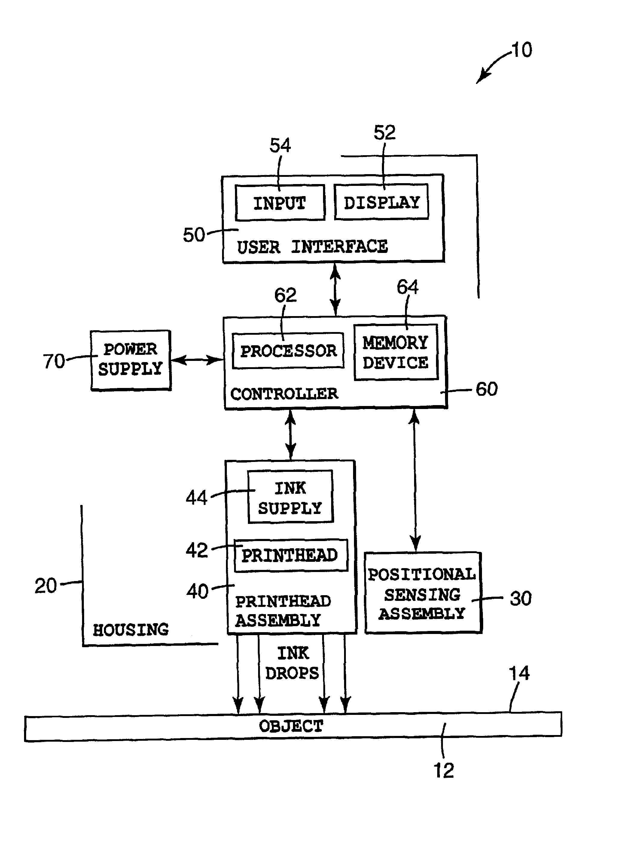
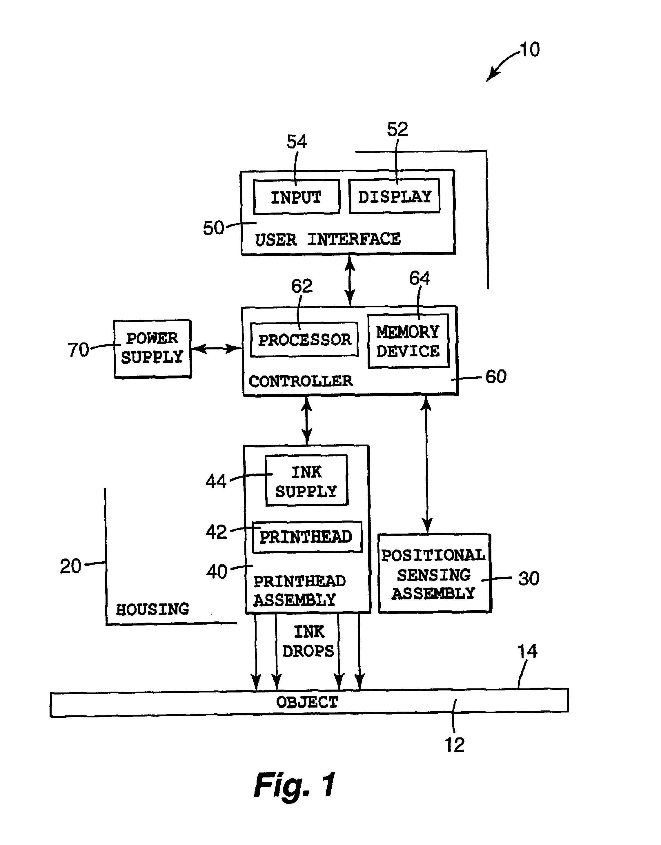
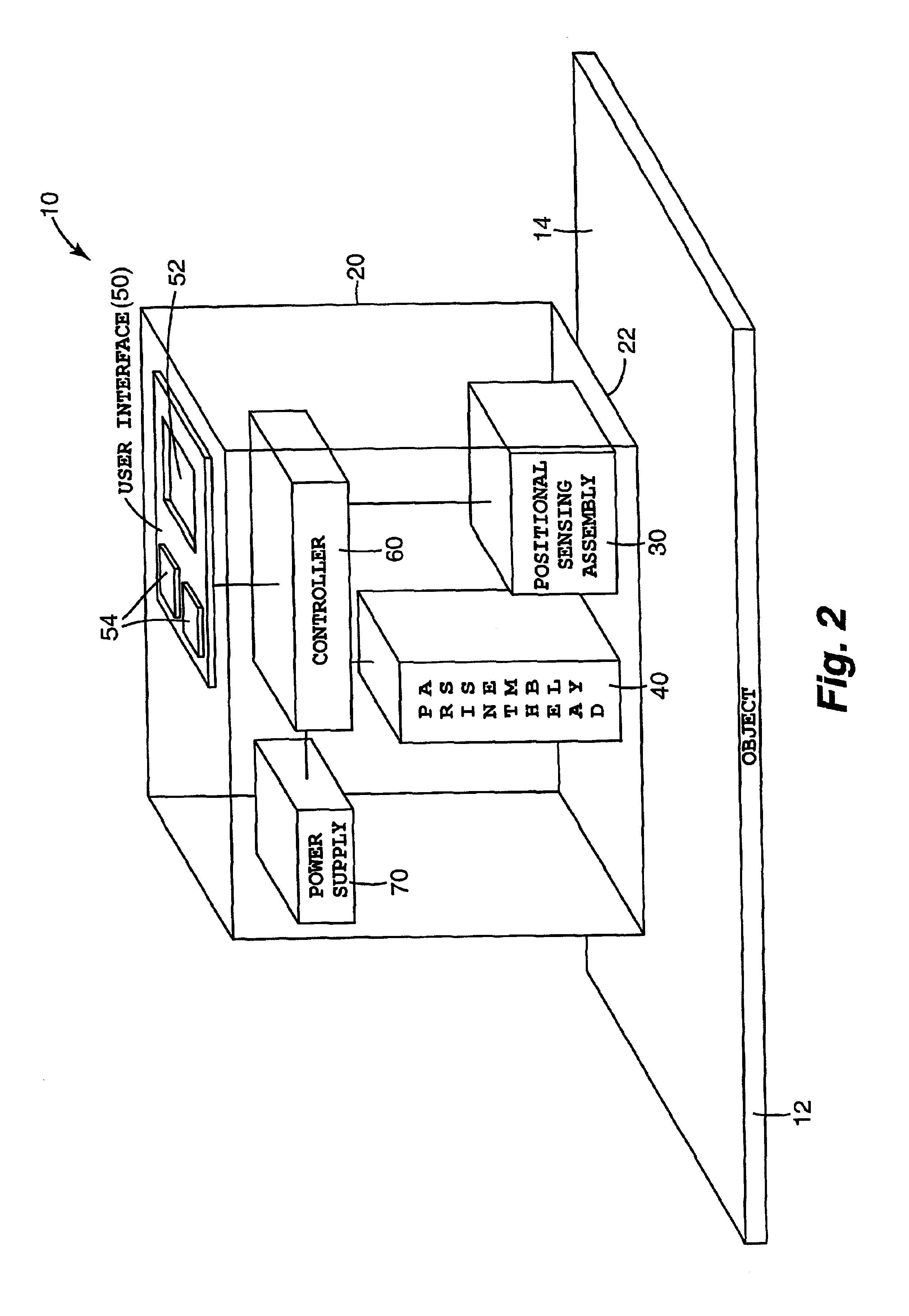
[0020]FIGS. 1 and 2 illustrate one embodim...


PUM


Abstract

A measurement and marking device includes a housing, a positional sensing assembly mounted in the housing, a printhead assembly mounted in the housing, and a controller mounted in the housing and communicating with the positional sensing assembly and the printhead assembly. The positional sensing assembly is adapted to sense a position of the housing relative to an object as the housing is moved along a surface of the object and the printhead assembly is adapted to print on the surface of the object as the housing is moved along the surface of the object. As such, the controller is adapted to operate the printhead assembly to print a mark on the surface of the object based on the position of the housing relative to the object as the housing is moved along the surface of the object.

Description

THE FIELD OF THE INVENTION[0001]The present invention relates generally to measurement systems and, more particularly to a hand-held device for measuring an object, marking the object with a measurement, and / or transferring a measurement of the object to another object.BACKGROUND OF THE INVENTION[0002]To transfer a measurement from a first object to a second object, a user typically follows a process of making and reading the measurement at the first object, recording the measurement by mentally remembering and / or physically writing down the measurement, and reproducing the measurement at the second object by marking the measurement on the second object. Conventional measurement devices for making the measurement include tape measures, scales or rulers, micrometers, etc. Conventional marking devices for recording and / or transferring the measurement include pencils, chalk lines, scribes, etc. Thus, the user must handle or operate a separate measurement device and a separate marking d...

Claims


Application Information

Patent Timeline
IPC IPC(8): G01B21/02G01B3/12
CPCG01B3/12G01B21/02
Inventor SAKSA, THOMAS A.
Owner HEWLETT PACKARD DEV CO LP
Learn More