
Disk drive apparatus and method for compensating for error in servo-information-recorded position between heads

Active Publication Date: 2005-09-20
KK TOSHIBA
View PDF11 Cites 15 Cited by
  • Summary
  • Abstract
  • Description
  • Claims
  • Application Information

AI Technical Summary

Benefits of technology

[0014]The present invention has been developed in light of the above, and aims to compensate for a displacement of a servo position if it occurs upon, for example, head selection in a disk drive, thereby minimizing degradation of the performance of the disk drive upon, for example, head selection.

Problems solved by technology

This servo information writing method is, however, inefficient.
Furthermore, a servo mark, as servo identification information contained in the servo information, may not be detected (servo mark absence), or the servo information may be detected at an erroneous timing (erroneous servo detection), which causes an erroneous output timing of a servo gate and hence a reduction of the seek performance.

Method used


Image

  • Disk drive apparatus and method for compensating for error in servo-information-recorded position between heads
  • Disk drive apparatus and method for compensating for error in servo-information-recorded position between heads
  • Disk drive apparatus and method for compensating for error in servo-information-recorded position between heads

Examples


Embodiment Construction

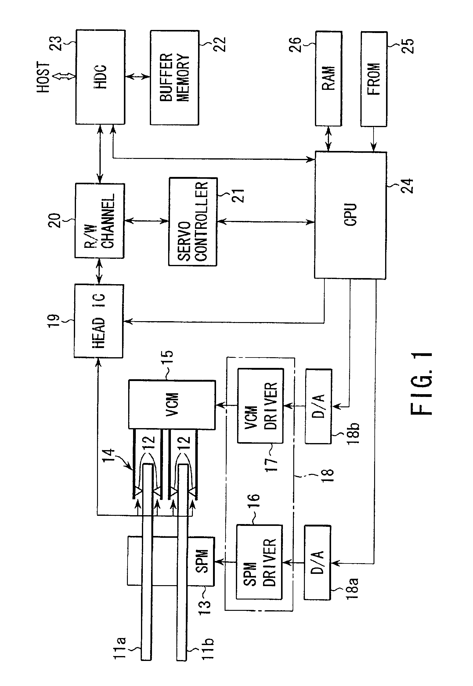
[0031]An embodiment in which the invention is applied to a hard disk drive will be described with reference to the accompanying drawings. FIG. 1 is a block diagram illustrating the configuration of the hard disk drive according to the embodiment of the invention. In the hard disk drive (HDD) shown in FIG. 1, a number (e.g. two) of disks (magnetic disk mediums) 11a and 11b, on which data is magnetically recorded, are stacked. Each disk 11i (i=a, b) has two (upper and lower) disk surfaces. At least one (e.g. both) of the two surfaces of each disk 11i serves as a recording surface for recording data. Heads (magnetic heads) 12, which are used to read / write data from / to each disk 11i (data reproduction / recording), are provided for the respective recording surfaces of each disk 11i. Suppose here that servo information is prerecorded by the pre-servo method on the disks 11a and 11b. The number of disks is not limited to two. It is sufficient if the HDD includes a plurality of stacked disks...


PUM


Abstract

In a first mode, an R / W channel starts to monitor read information to thereby detect a servo mark contained in servo information, each time a servo controller generates a servo gate pulse. Upon detecting the servo mark, the R / W channel detects, from the read information, position information contained in the servo information and following the servo mark, at a timing determined by the detection timing of the servo mark. When the first mode has been switched to a second mode, the R / W channel detects the servo mark and position information using the synchronous method.

Description

CROSS-REFERENCE TO RELATED APPLICATIONS[0001]This application is based upon and claims the benefit of priority from the prior Japanese Patent Application No. 2001-235107, filed Aug. 2, 2001, the entire contents of which are incorporated herein by reference.BACKGROUND OF THE INVENTION[0002]1. Field of the Invention[0003]The present invention relates to a disk drive apparatus equipped with a plurality of disks on which servo information is prerecorded, and more particularly to a disk drive apparatus and method suitable for compensating for non-continuity of servo information that occurs, for example, when one head is selected.[0004]2. Description of the Related Art[0005]A hard disk drive is known as a disk drive using disks as storage mediums. In a hard disk, in general, a head is moved to a target track by seek control and positioned in a target area on the target track, on the basis of servo information prerecorded on each disk.[0006]In the prior art, servo information is written to...

Claims


Application Information

Patent Timeline
IPC IPC(8): G11B27/30G11B27/36G11B5/596G11B21/08G11B21/10
CPCG11B5/59611G11B27/3027G11B27/36G11B2220/20
Inventor TODA, AKIO
Owner KK TOSHIBA
Learn More