
Intravascular catheter with axial member

Inactive Publication Date: 2005-09-13
BOSTON SCI SCIMED INC
View PDF103 Cites 51 Cited by
  • Summary
  • Abstract
  • Description
  • Claims
  • Application Information

AI Technical Summary

Benefits of technology

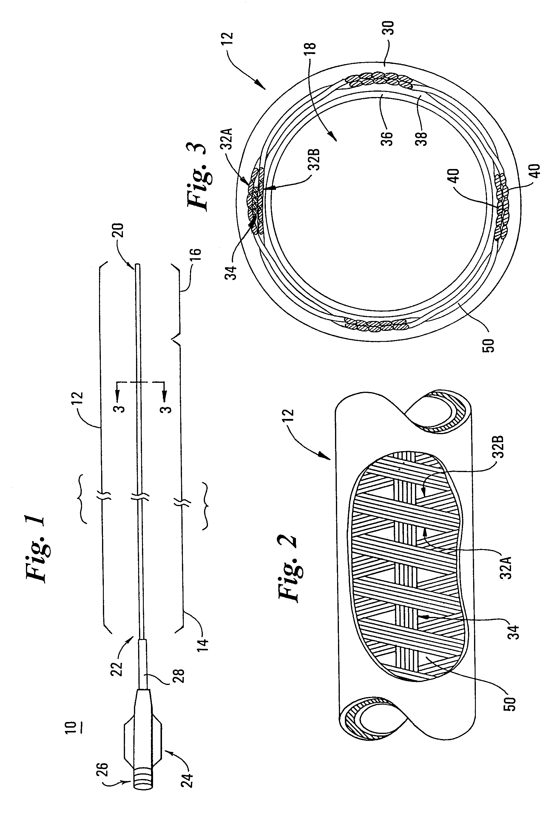
[0012]The present invention overcomes these disadvantages by providing an intravascular catheter that includes a braid reinforcement with an axial wire or fiber disposed between the helical members that form the braid. By placing the axial member between the helical members, the axial member does not create a protrusion on either side of the braid. In addition, the axial member does not become fixed to any polymer layer adjacent the braid. Thus, the present invention provides the benefits of an axial member, but without the undesirable effects of friction caused by an axial protrusion and without the undesirable effects of limited flexure caused by an adjacent polymer layer becoming fixed to the axial member. Specifically, by utilizing an axial member, the present invention provides a catheter shaft that resists elongation when placed in tension. By resisting elongation, the intravascular catheter of the present invention maintains one-to-one correspondence in axial manipulation thereby maintaining precise control of the catheter.
[0014]The helical members that form the braid may each comprise polymeric material, a metallic material, or a combination thereof. Similarly, the axial member may comprise a polymeric material or a metallic material. If a polymeric material is utilized for the helical members or the axial member, then each member may comprise a plurality of monofilaments such as LCP. The monofilaments may be held together statically thereby eliminating the need for a binding material that might otherwise add to the profile of the members. To further minimize profile, the monofilaments may be arranged side-by-side to collectively define a flat ribbon or cable.

Problems solved by technology

A protrusion along the inside surface of the catheter may not be desirable because it may create friction or bias with devices inserted therein (e.g., guidewires).
A protrusion along the outside surface of the catheter may not be desirable because it may create friction, bias or prevent adequate sealing with devices that the catheter is inserted into (e.g., introducer sheaths, compression fittings, etc.).
Fixing the longitudinal warp members to the adjacent polymeric layer may not be desirable because it may limit relative movement and flexure therebetween.
Limiting relative movement and flexure may cause excessive stiffness in one or more planes of flexure.
This may cause difficulties in manipulating and navigating the catheter through tortuous vasculature, which is clearly undesirable.

Method used


Image

  • Intravascular catheter with axial member

Examples


Embodiment Construction

[0020]The following detailed description should be read with reference to the drawings in which similar elements in different drawings are numbered the same. The drawings, which are not necessarily to scale, depict illustrative embodiments and are not intended to limit the scope of the invention.

[0021]FIG. 1 illustrates intravascular catheter 10 in accordance with the present invention. Catheter 10 includes an elongate shaft 12 having a proximal region 14 and a distal region 16. The catheter 10 includes a lumen 18 (as best seen in FIG. 3) extending through the entire length of the elongate shaft 12 to an opening at the distal end 20 of the shaft 12. Catheter 10 may have, for example, a length of 80–150 cm and an outside diameter of approximately 3F.

[0022]A manifold 24 is connected to the proximal end 22 of the shaft 12 which includes an interior (not visible) in fluid communication with the lumen 18 of the elongate shaft 12. The manifold 24 includes a standard fitting 26 for connect...


PUM


Abstract

An intravascular catheter having a shaft, at least a portion of which includes a braid reinforcement with an axial wire or fiber disposed between the helical members that form the braid. The axial member prevents the elongation of the shaft of the catheter thereby maintaining one-to-one correspondence in axial manipulation of the catheter, even when the shaft is placed in tension. By positioning the axial member between the helical members, the axial member does not create a protrusion and does not become fixed to any adjacent polymer layer. Thus, the axial member limits axial strain of the catheter, without creating the undesirable effects of friction caused by an axial protrusion and without creating the undesirable effects of limited flexure caused by an adjacent polymer layer becoming fixed to the axial member.

Description

CROSS REFERENCE TO RELATED APPLICATIONS[0001]The present invention is related to U.S. patent application Ser. No. 09 / 234,203, filed Jan. 20, 1999, entitled “INTRAVASCULAR CATHETER WITH COMPOSITE REINFORCEMENT”; and U.S. Patent Application No. (unknown), filed on even date herewith, entitled “INTRAVASCULAR CATHETER WITH MULTIPLE AXIAL MEMBERS”, the entire disclosures of which are hereby incorporated by reference.FIELD OF THE INVENTION[0002]The present invention generally relates to intravascular catheters. More specifically, the present invention relates to intravascular catheters having braid reinforcement.BACKGROUND OF THE INVENTION[0003]Intravascular catheters are used in a wide variety of relatively non-invasive medical procedures. Such intravascular catheters may be used for diagnostic or therapeutic purposes. Generally, an intravascular catheter allows a physician to remotely perform a medical procedure by inserting the catheter into the vascular system of the patient at a loca...

Claims


Application Information

Patent Timeline
IPC IPC(8): A61M25/00
CPCA61M25/005A61M25/0053
Inventor SCHAEFER, DEAN A.PAULK, DAVIDANDERSON, STEVEN M.
Owner BOSTON SCI SCIMED INC
Learn More