
Plane plate vibration device and switch employing the same

a vibration device and switch technology, applied in the field of input devices, can solve the problems of inability to provide a sufficient gap between the upper movable plate and the user, inability to recognize a pushdown, and inability to give the feeling of click

Active Publication Date: 2005-08-30
FUJITSU COMPONENENT LTD
View PDF4 Cites 90 Cited by
  • Summary
  • Abstract
  • Description
  • Claims
  • Application Information

AI Technical Summary

Problems solved by technology

In the case where the above-mentioned panel-shaped input devices, are used as an input switch, a plane switch such as a touch panel does not give a feeling of click as if a mechanical switch were pushed down.
This is a drawback in that a user cannot recognize a pushdown.
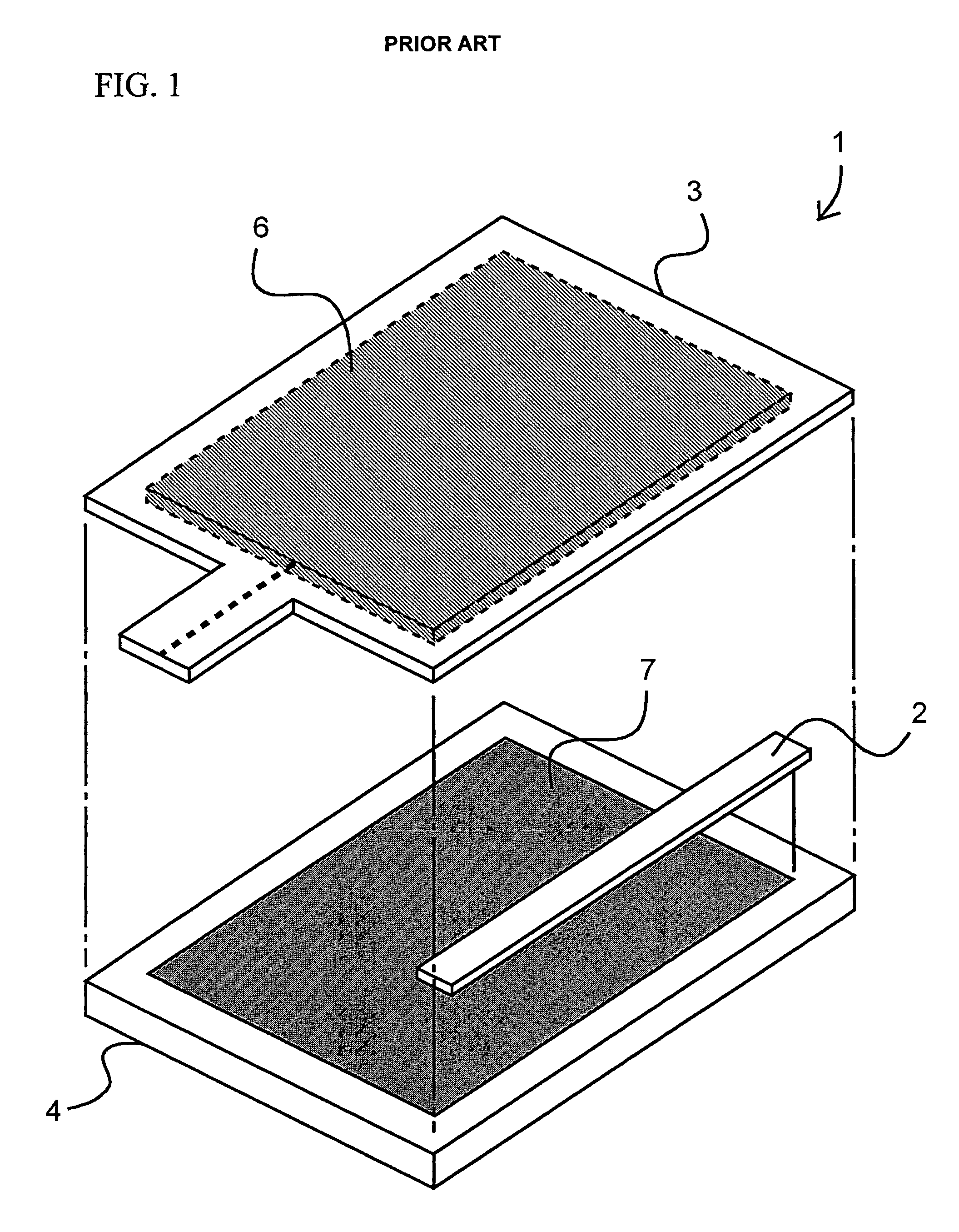
This bonding structure makes it impossible to provide a sufficient gap between the upper movable plate 3 and the lower supporting substrate 4.
This makes it impossible to give the feeling of click, when the panel is pushed down.
There is a problem in that the device disclosed in Document 2 cannot be used as the input device, because it is hard to recognize a display device or electric decoration, if the display device or electric decoration is provided on a backside of the protruded surface 11.

Method used


Image

  • Plane plate vibration device and switch employing the same
  • Plane plate vibration device and switch employing the same
  • Plane plate vibration device and switch employing the same

Examples


first embodiment

[0029]A description will be given of a first embodiment of the present invention, with reference to drawings. FIG. 3A is a perspective view of a laminated structure of a plane plate vibration device in accordance with the first embodiment of the present invention. FIG. 3B is a cross-sectional view taken along a line A—A shown in FIG. 3A. A plane plate vibration device 100 includes a fixing member 101, a touch panel 102, a coil portion 103 having a first coil 103a and a second coil 103b, and a frame-shaped base 104. The fixing member 101 has a shape of substantially rectangular frame, is made of an elastic body such as rubber, and has an opening in the center to secure a circumference portion thereof excluding an input surface of the touch panel 102. The fixing member 101 may be divided and arranged partially on the circumference portion of the touch panel 102. Referring to FIG. 3B, the circumference portion on the top face of the touch panel 102 is bonded together with a bottom face...


PUM

PropertyMeasurementUnit
currentaaaaaaaaaa
circumferenceaaaaaaaaaa
magnetic fieldaaaaaaaaaa

Abstract

A plane plate vibration device includes a plane plate, a coil portion having a first coil and a second coil, the first coil being wound on a circumference of the plane plate in parallel with the plane plate, the second coil being wound along inside of the first coil in parallel with the plane plate, and magnetic field generating mechanisms that are provided in parallel with the plane plate and generate magnetic fields in directions perpendicular to directions of currents respectively flowing through the first coil and the second coil. The currents flow through the first coil and the second coil in reverse directions, the directions of magnetic fields perpendicular to the currents respectively flowing through the first coil and the second coil give forces in the same direction, and the plane plate vibrates in a direction of thickness by adjusting the currents respectively flowing through the first coil and the second coil.

Description

BACKGROUND OF THE INVENTION[0001]1. Field of the Invention[0002]This invention generally relates to an input device such as a touch panel, switch, or the like. The touch panel is used for detecting coordinates of a position pushed by, for example, a pen, a finger, or the like, and the input device is used for detecting a position inputted by a finger or the like.[0003]2. Description of the Related Art[0004]Conventionally, panel-shaped input devices named touch panel input device and touch pad input device have been proposed. The touch panel input device includes a display overlapping a touch sensor. The touch pad is used with a personal computer. Information to the above-mentioned panel-shaped input devices is generated by touching a position that corresponds to, for example, buttons displayed on a screen with an attached pen or by touching inside an operation range at certain intervals.[0005]In the case where the above-mentioned panel-shaped input devices, are used as an input swit...

Claims


Application Information

Patent Timeline
Patent Type & Authority Patents(United States)
IPC IPC(8): G06F3/033H01F7/08G06F3/03H01H51/22G06F3/041H01H13/85
CPCH01H13/85H01H2215/05
Inventor NAKAMURA, AKIOSAKURAI, SATOSHIKURASHIMA, SHIGEMIYATSU, NOBUOAKIEDA, SHINICHIRO
Owner FUJITSU COMPONENENT LTD
Learn More