Railroad e-clip removal system
- Summary
- Abstract
- Description
- Claims
- Application Information
AI Technical Summary
Benefits of technology
Problems solved by technology
Method used
Image

Examples
Embodiment Construction
A. Overview
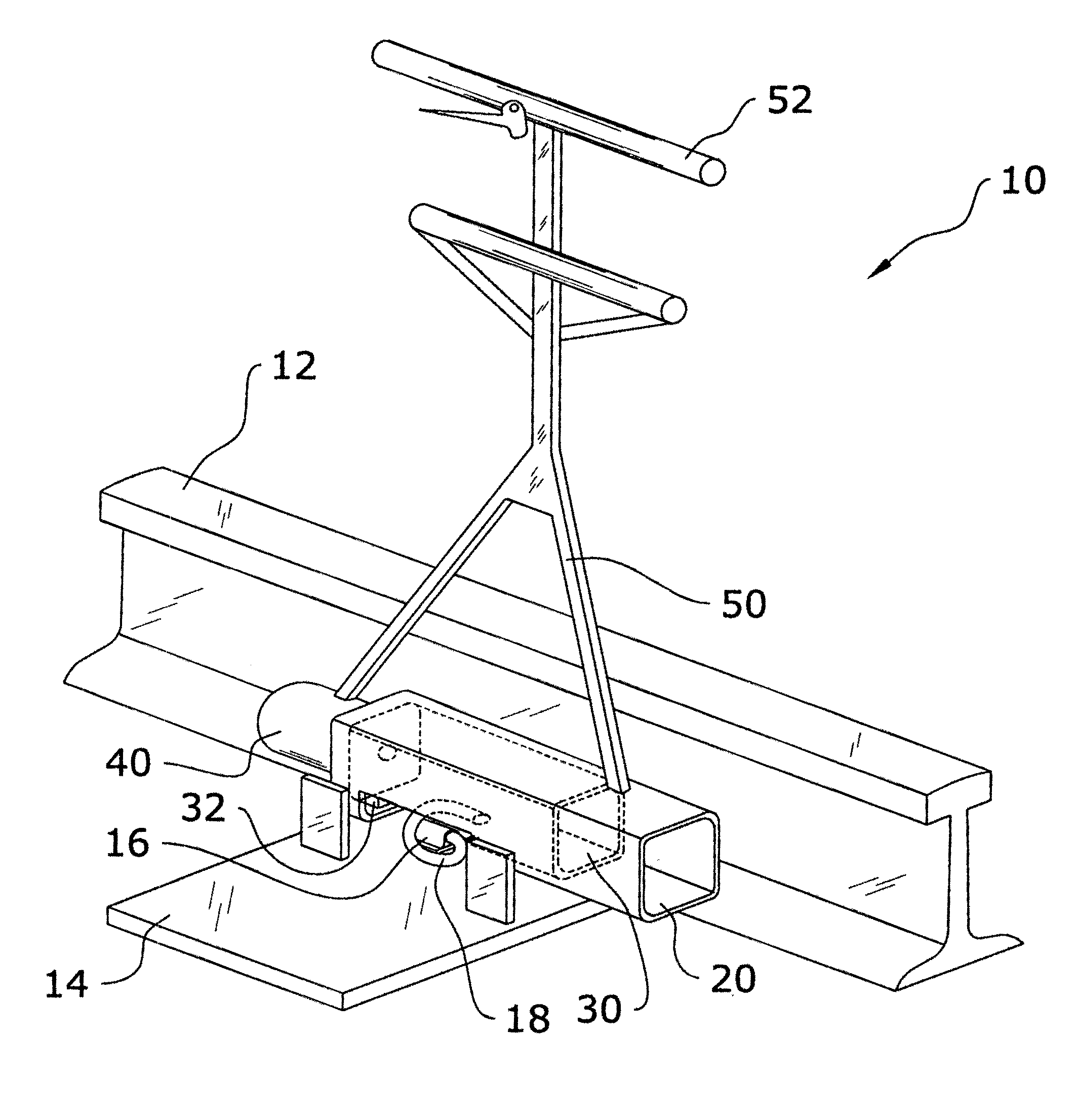
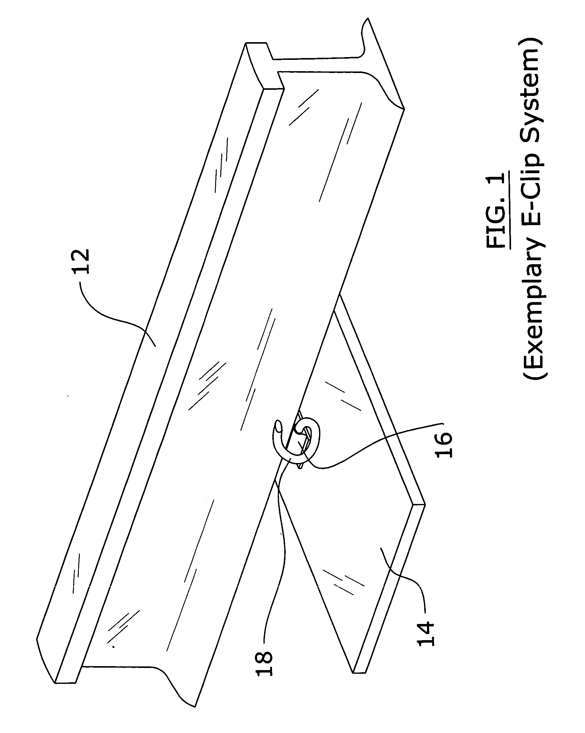
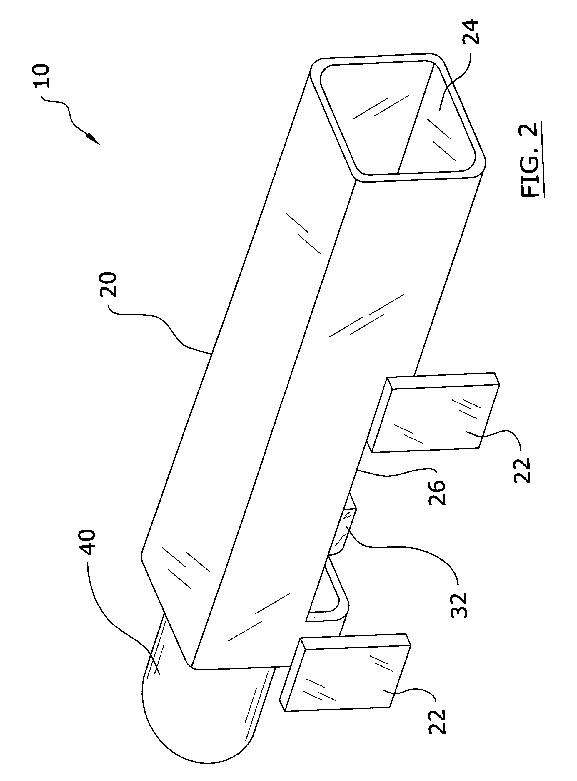
[0033]Turning now descriptively to the drawings, in which similar reference characters denote similar elements throughout the several views, FIGS. 1 through 11 illustrate a railroad e-clip removal system 10, which comprises an outer tube 20 with an outer cutout 26, an inner tube 30 slidably positioned within a lumen 24 of the outer tube 20, an inner cutout 34 within the inner tube 30 having an engaging portion 32, and an actuator unit 40 attached to the tubes for extending / retracting the inner tube 30 within the outer tube 20. The engaging portion 32 of the inert tube engages a portion of an e-clip 18 when the actuator unit 40 is extended thereby forcing the e-clip 18 from a tubular support member 16 attached to a rail pad 14. The e-clip 18 is thereby safely and efficiently removed from the railroad track.
B. Outer Tube
[0034]The outer tube 20 has an elongate structure with an outer cutout 26 as best shown in FIG. 3 of the drawings. The outer tube 20 may have various cross ...
PUM
| Property | Measurement | Unit |
|---|---|---|
| Size | aaaaa | aaaaa |
| Shape | aaaaa | aaaaa |
Abstract
Description
Claims
Application Information
 - R&D
- Intellectual Property
- Life Sciences
- Materials
- Tech Scout
- Unparalleled Data Quality
- Higher Quality Content
- 60% Fewer Hallucinations
Browse by: Latest US Patents, China's latest patents, Technical Efficacy Thesaurus, Application Domain, Technology Topic, Popular Technical Reports.
© 2025 PatSnap. All rights reserved.Legal|Privacy policy|Modern Slavery Act Transparency Statement|Sitemap|About US| Contact US: help@patsnap.com