Oscillation state discrimination circuit and oscillation control circuit adapted to oscillation circuit

Inactive Publication Date: 2005-08-16
YAMAHA CORP
View PDF3 Cites 1 Cited by
  • Summary
  • Abstract
  • Description
  • Claims
  • Application Information

AI Technical Summary

Benefits of technology

[0016]It is an object of the invention to provide an oscillation state discrimination circuit and an oscillation control circuit, which can rapidly switch over a damping resistance upon discrimination of an oscillation state of the oscillation circuit, wherein it is possible to prevent the oscillation circuit from producing an unstable oscillation signal, thus preventing an external device from operating abnormally.

Problems solved by technology

Although quartz oscillators are reduced in sizes, they may be easily damaged due to excitation signals applied thereto.
Damping resistors operate to suppress excitations of quartz oscillators, wherein they have a drawback in that a relatively long time is required to stabilize oscillation states particularly in initial periods of oscillations just after applying electric power therefor.
This causes a relatively intense stress on the quartz oscillator XT, which may be easily damaged.
In addition, when an external device inputs an oscillation signal that is produced by the oscillation circuit whose oscillation is unstable, there is a possibility that the external device may operate abnormally.

Method used


Image

  • Oscillation state discrimination circuit and oscillation control circuit adapted to oscillation circuit
  • Oscillation state discrimination circuit and oscillation control circuit adapted to oscillation circuit
  • Oscillation state discrimination circuit and oscillation control circuit adapted to oscillation circuit

Examples


first embodiment

1. First Embodiment

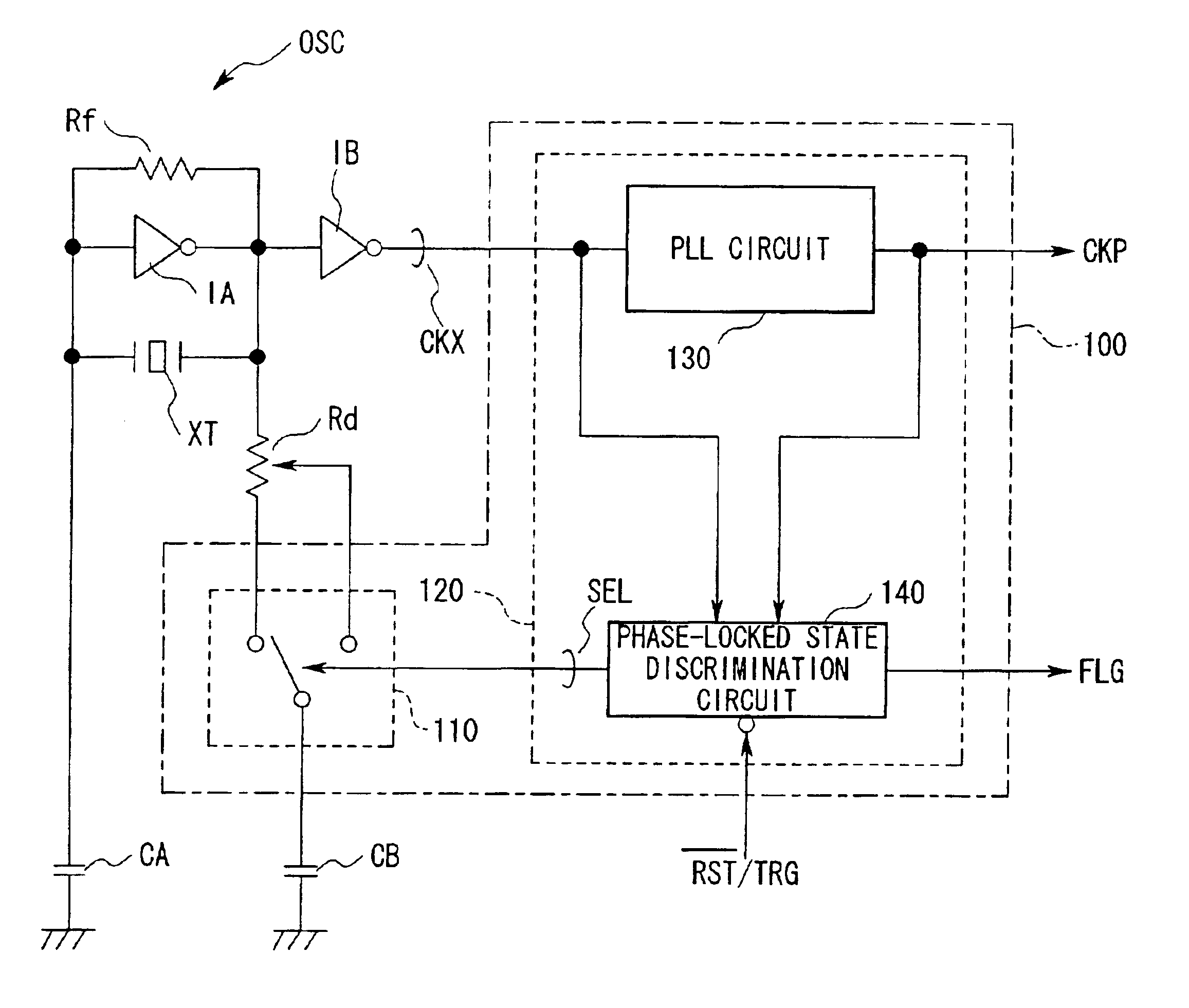
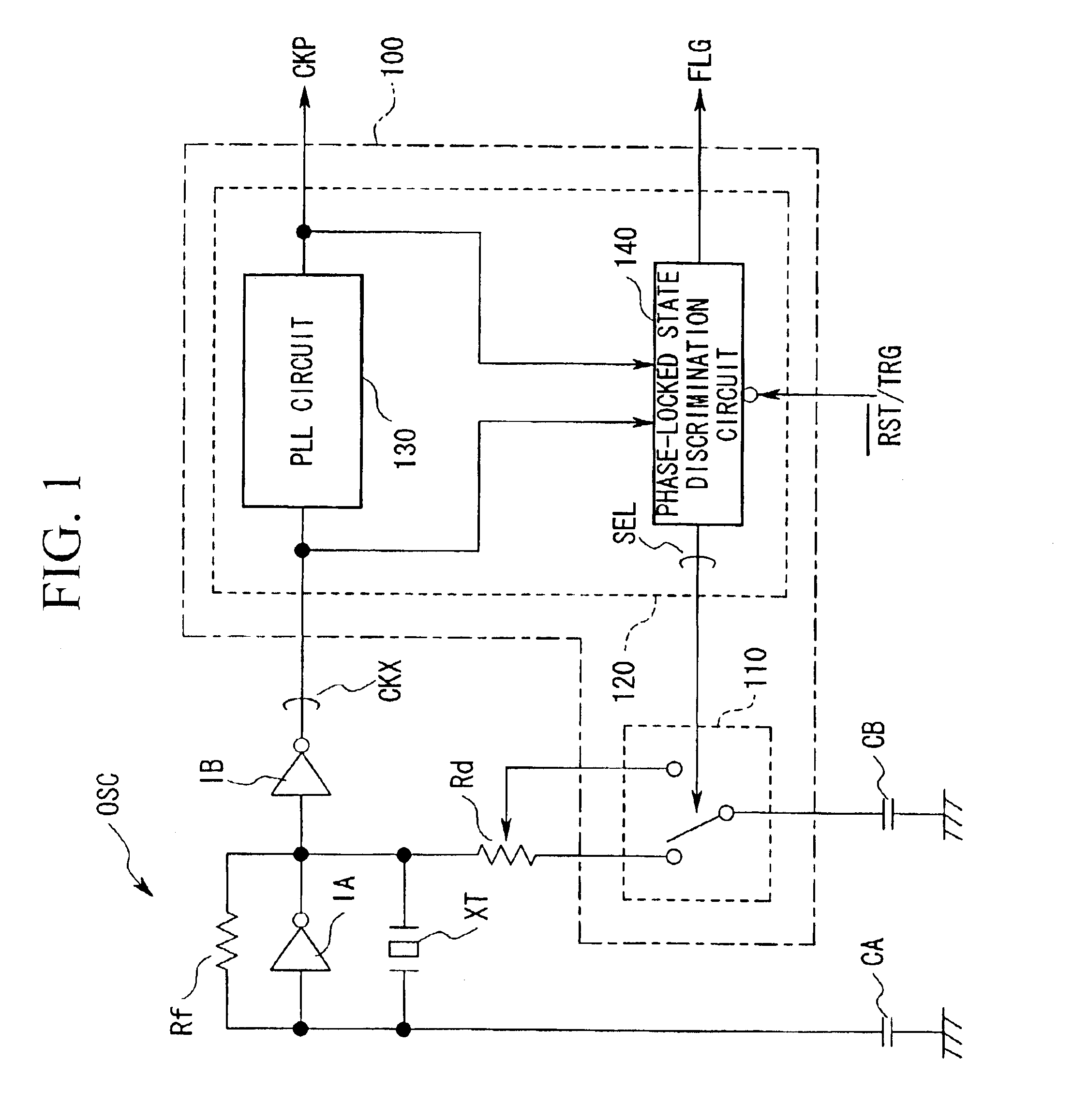
[0066]FIG. 1 is a circuit diagram including circuit blocks in which an oscillation control circuit is adapted to an oscillation circuit in accordance with a first embodiment of the invention. That is, an oscillation control circuit 100 controls an oscillation state of an oscillation circuit OSC by switching over a damping resistance Rd, wherein it comprises a switch 110 and an oscillation state discrimination circuit 120, which further comprises a PLL (Phase-Locked Loop) circuit 130 and a phase-locked state discrimination circuit 140. The configuration of the oscillation circuit OSC shown in FIG. 1 is basically identical to that of the aforementioned oscillation circuit shown in FIG. 13, wherein parts identical to those shown in FIG. 13 are designated by the same reference numerals; hence, the detailed description thereof will be omitted as necessary, whereas the switch 110 corresponding to the aforementioned switch SW is used as a constituent element of the oscil...

second embodiment

2. Second Embodiment

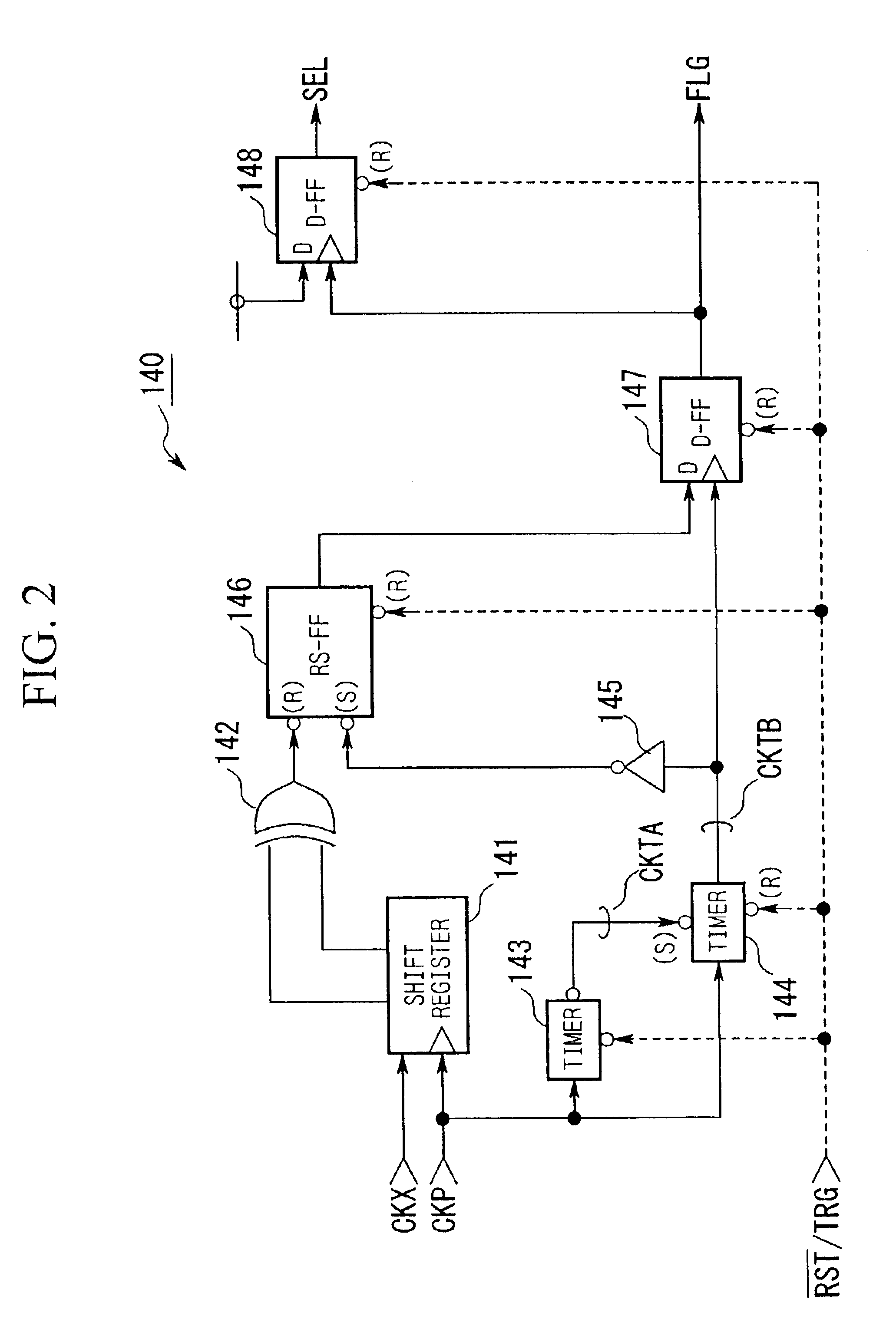
[0100]Next, a second embodiment will be described in detail, wherein the second embodiment is basically similar to the first embodiment except that the phase-locked state discrimination circuit 140 shown in FIGS. 1 and 2 is replaced with a discrimination circuit 150 shown in FIG. 6. Compared with the phase-locked state discrimination circuit 140 of FIG. 2, the discrimination circuit 150 of FIG. 6 further comprises a timer 151 and a NOR circuit 152 (having negated inputs), wherein parts identical to those shown in FIG. 2 are designated by the same reference numerals, and the description thereof will be omitted as necessary. Specifically, the aforementioned signal CKTB output from the timer 144 is supplied to a clock terminal of the timer 151, an output terminal of which is connected to the clock terminal of the D flip-flop 148. In addition, the aforementioned signal FLG output from the D flip-flop 147 is supplied to a first input terminal of the NOR circuit 152, t...

third embodiment

3. Third Embodiment

[0109]Next, a third embodiment will be described in detail. In the first and second embodiments, the damping resistance Rd is changed over upon discrimination whether or not the oscillation circuit OSC performs oscillation in a stable manner. The third embodiment is characterized in that a prescribed time period is measured using a timer with respect to the clock signal CKP so as to restore the damping resistance Rd to original resistance, wherein the timer is initialized (or reset) if oscillation is not stabilized so that the timer performs again time measurement.

[0110]The third embodiment is basically similar to the first embodiment except that the phase-locked state discrimination circuit 140 of the oscillation control circuit 100 shown in FIG. 1 is replaced with a phase-locked state discrimination circuit 200 shown in FIG. 8, wherein a shift register 201 and a decode circuit 202 may substantially match the aforementioned shift register 141 and the exclusive-or...


PUM


Abstract

An oscillation control circuit comprising a PLL circuit and a phase-locked state discrimination circuit is adapted to an oscillation circuit that performs oscillation to produce an oscillation signal (CKX) when supply voltage is applied thereto. The PLL circuit produces a clock signal (CKP) whose frequency is a multiple of the frequency of the oscillation signal, wherein it controls the clock signal to be synchronized with the oscillation signal in phase. The phase-locked state discrimination circuit discriminates whether or not the PLL circuit is placed in a phase-locked state on the basis of a phase relationship between the oscillation signal and clock signal. Based on a discrimination result, a damping resistance adapted to the oscillation circuit is switched over. That is, the damping resistance (Rd) is reduced to cope with an unstable state of oscillation; then, it is restored to an original resistance thereof when oscillation is certainly stabilized.

Description

BACKGROUND OF THE INVENTION[0001]1. Field of the Invention[0002]This invention relates to oscillation state discrimination circuits that discriminate oscillation states of oscillation circuits such as crystal oscillators. In addition, this invention also relates to oscillation control circuits that control oscillation states and oscillation outputs of oscillation circuits, particularly in initial periods of oscillation.[0003]2. Description of the Related Art[0004]Conventionally, a variety of oscillation circuits using quartz oscillators (namely, crystal oscillators) have been widely used and installed in electronic devices, wherein quartz oscillators are reduced in sizes to match recent electronic devices, which tend to be compact and downsized to satisfy consumers' demands. Although quartz oscillators are reduced in sizes, they may be easily damaged due to excitation signals applied thereto. For this reason, so-called damping resistors are arranged for oscillation circuits to suppr...

Claims


Application Information

Patent Timeline
IPC IPC(8): H03L7/08H03L3/00H03L7/095H03L7/10H03B5/06H03B5/32
CPCH03L3/00H03L7/0807H03L7/095H03L7/10Y10S331/02
Inventor ITO, MASAHIRO
Owner YAMAHA CORP
Why Eureka
Try Eureka