Stacker for a printer

a printer and stamping technology, applied in stamping, instruments, transportation and packaging, etc., can solve the problems of long queues at ticket sales counters, large number of tickets purchased by each person in the line, and long delays in ticket sales

Inactive Publication Date: 2005-08-16
TRANSACT TECH
View PDF13 Cites 5 Cited by
  • Summary
  • Abstract
  • Description
  • Claims
  • Application Information

AI Technical Summary

Benefits of technology

[0006]It is a primary object of the present invention to improve transaction-based printers, such as POS printers, ticket printers, and the like. It is a further object to provide a gaming and lottery printer that will help speed the sale of tickets.
[0007]It is a still further object of the present invention to reduce the amount of manual handling required to produce a series of tickets, vouchers, coupons or other printed substrates purchased under one sale transaction.
[0010]In another embodiment, a sheet drive is provided for advancing sheet material from a spool through a printing station and then registering the sheet in a stationary condition within a cutting station. A cutter, such as a rotary cutter, is mounted within the cutting station. The cutter can include, for example, a stationary blade and a movable blade for severing the registered sheet from the spool. A kicker element (e.g., a kicker wheel) is mounted upon a shaft within the cutting station. A clutch allows the kicker element to freely rotate in one direction as the sheet is forwarded into the cutting station. A drive system that is associated with the cutter control mechanism reverses the direction of rotation of the kicker element once the cutting operation is completed, locking the clutch and thus causing the severed sheet to be kicked into a collecting bin.

Problems solved by technology

For example, when a winning lottery prize becomes relatively large, the lines at ticket sales counters become long.
In addition, the number of tickets purchased by each person in the line can be relatively large.
This can be a time consuming procedure leading to errors being made and long delays in ticket sales.

Method used


Image

  • Stacker for a printer
  • Stacker for a printer
  • Stacker for a printer

Examples


Embodiment Construction

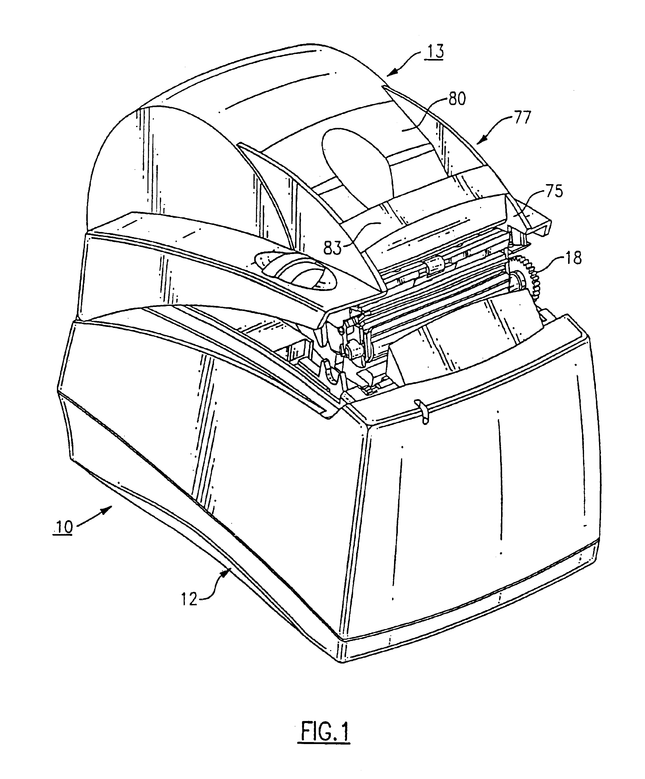
[0017]Turning now to the drawings, there is illustrated a printer, generally referenced 10, that embodies the teachings of the present invention. It is noted that the illustrated printer is only one example embodiment of a printer that can incorporate the features of the present invention.

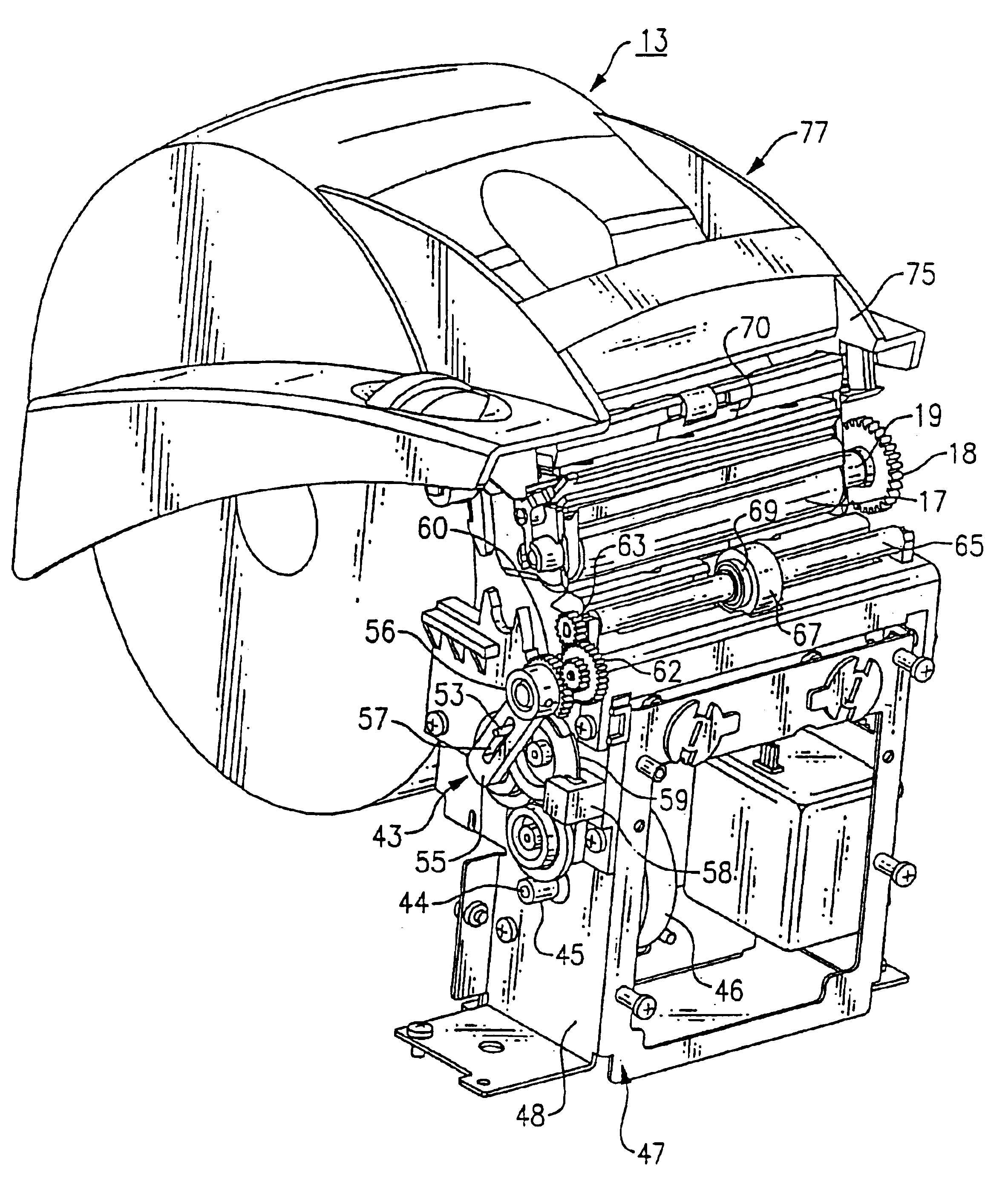
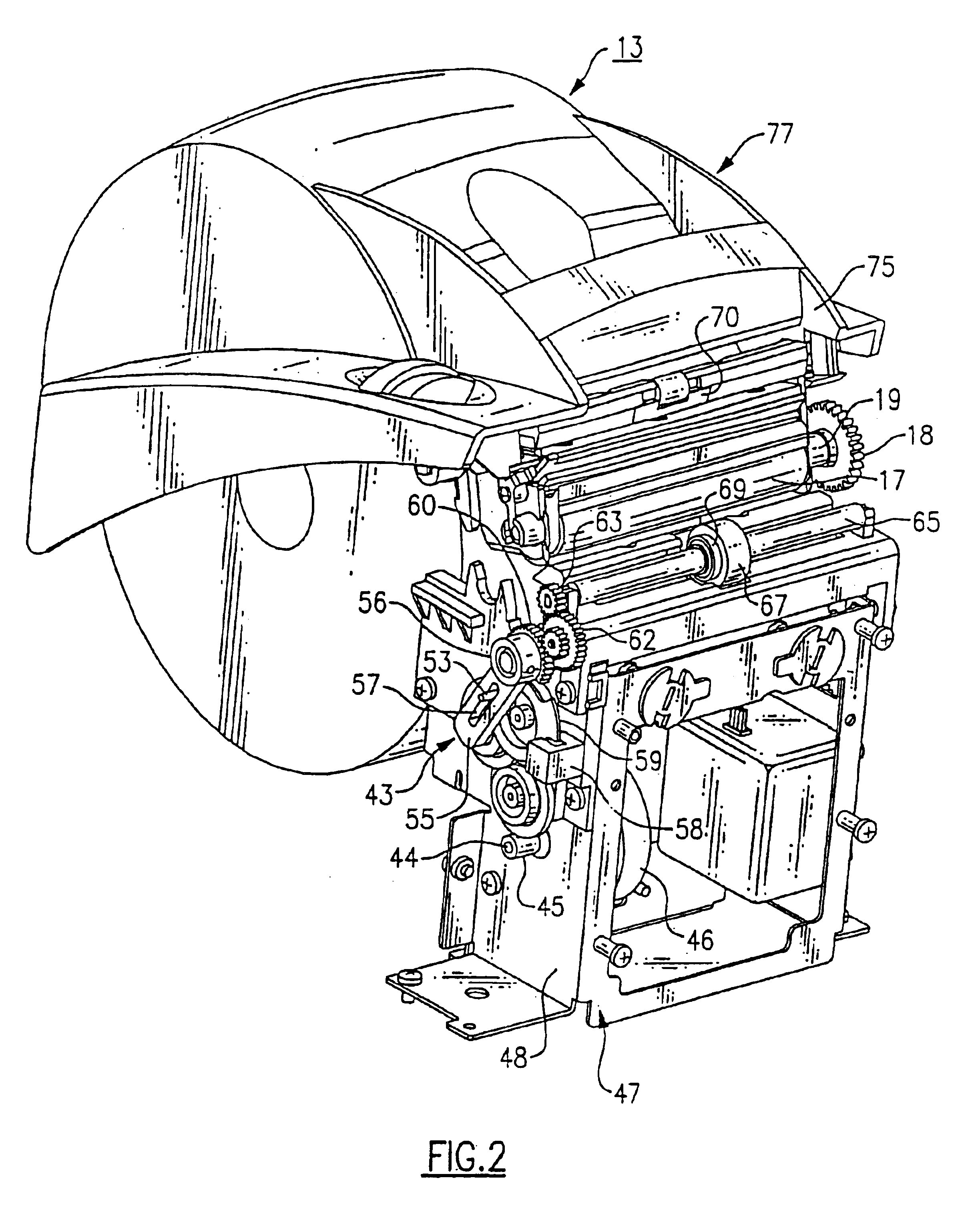
[0018]The printer 10 includes a rectangular shaped housing 12 upon which a hinged cover 13 is provided. The hinge is located at the back of the housing cover so that the cover can swing upwardly and rearwardly to provide ready access to a paper bin located in the rear of the printer housing. The bin is configured to accept a supply spool of paper 15, which serves as the substrate for printing a ticket, voucher, coupon or the like. A main feed roller 17 is rotatably mounted in the cover and contains a gear 18 that is affixed to one end of feed roller shaft 19. The feed roller gear 18 is arranged to mesh with an intermediate or idler gear 20 when the cover is closed. The idler gear 20 forms part of t...


PUM


Abstract

A transaction-based printer has a sheet drive for forwarding a sheet through a printing station to a cutting station where the sheet is severed from a spool by a rotary cutter. A kicker element is mounted in the cutting station. Movement of the kicker element is coordinated through the cutter drive with that of the rotary cutter so that the severed sheet is kicked into a bin located in the top cover of the printer. The printer can be, for example, an ink-jet, dot matrix, dye sublimation or thermal printer used to print tickets, vouchers, coupons or the like.

Description

[0001]This application is a divisional of U.S. patent application Ser. No. 10 / 379,373 filed on Mar. 4, 2003, now U.S. Pat. No. 6,827,515.FIELD OF THE INVENTION[0002]This invention relates to a stacker for a printer and, in particular, to a stacker for paper tickets, vouchers and the like that exit a transaction-based printer. The invention is particularly useful, e.g., in connection with gaming and lottery printers that provide racetrack tickets, lottery tickets or the like.BACKGROUND OF THE INVENTION[0003]High speed printers, such as inkjet, thermal, dye sublimation and dot matrix printers are used to provide vouchers, coupons, tickets, receipts and the like to consumers. For example, when a winning lottery prize becomes relatively large, the lines at ticket sales counters become long. In addition, the number of tickets purchased by each person in the line can be relatively large. Heretofore, most point of sales (POS) and other transaction-based printers have been designed to issue...

Claims


Application Information

Patent Timeline
Patent Type & Authority Patents(United States)
IPC IPC(8): B65H35/00B65H29/22G07B5/00G07B5/02G07B1/00B41J11/42B41J11/66B41J11/70B41J15/04
CPCB41J11/42B41J11/70B41J15/042B65H29/22B65H35/0006G07B1/00G07B5/02B65H2403/72B65H2404/153B65H2701/1936Y10S271/902B41J11/66
Inventor HARRIS, BRUCEWEEKS, DAVID E.
Owner TRANSACT TECH
Why Eureka
Try Eureka