
System and methods for cervical spinal fusion

a cervical spine and spinal cord technology, applied in the field of spinal surgery, can solve the problems of accelerating the degeneration of vertebrae, affecting the stability of the patient's intervertebral space, and affecting the patient's recovery,

Inactive Publication Date: 2005-08-02
NUVASIVE
View PDF194 Cites 324 Cited by
  • Summary
  • Abstract
  • Description
  • Claims
  • Application Information

AI Technical Summary

Benefits of technology

The present invention provides a system for spinal fusion that overcomes the drawbacks of previous methods. The system includes a spinal implant and an implant insertion tool. The spinal implant has top and bottom sides, lateral sides, a proximal side, and a distal side, with the top and bottom sides having a polygonal shape. The implant has at least two apertures that create a purchase region for securely attaching the implant to the spine. The insertion tool has an elongate fork member and a tubular lock member. The elongate fork member has clamping arms that engage the apertures of the spinal implant. The tubular lock member is inserted through the intervertebral space and rotated to secure the spinal implant. The system provides a compressive force on the purchase region to securely fuse the spine. The technical effects of the invention include improved spinal fusion and a more secure and effective spinal implant insertion tool.

Problems solved by technology

Such degeneration can occur as a result of aging or trauma and typically results in pinched or damaged nerves between or proximal to the adjacent vertebrae.
Moreover, such disc degeneration causes shifting of the loading along the patient's spinal column, which in turn further accelerates the vertebral degeneration.
A common problem with the existing intervertebral spinal inserts is that they do not provide stabilization in two perpendicular directions in the plane of the patient's intervertebral space.
Another disadvantage is that, during such major surgery, the actual insertion of the intervertebral insert requires distraction of the adjacent vertebrae to first open a sufficiently large passage for the insertion of the insert therebetween.
Moreover, the shape of current inserts does not take advantage of the natural contoured shape of the adjacent vertebral surfaces.
When implanting bony implants, however, it may be difficult to visualize the implant in this fashion.

Method used


Image

  • System and methods for cervical spinal fusion
  • System and methods for cervical spinal fusion
  • System and methods for cervical spinal fusion

Examples


Embodiment Construction

[0025]Illustrative embodiments of the invention are described below. In the interest of clarity, not all features of an actual implementation are described in this specification. It will of course be appreciated that in the development of any such actual embodiment, numerous implementation-specific decisions must be made to achieve the developers' specific goals, such as compliance with apparatus-related and business-related constraints, which will vary from one implementation to another. Moreover, it will be appreciated that such a development effort might be complex and time-consuming, but would nevertheless be a routine undertaking for those of ordinary skill in the art having the benefit of this disclosure. The apparatus disclosed herein boast a variety of inventive features and components that warrant patent protection, both individually and in combination.

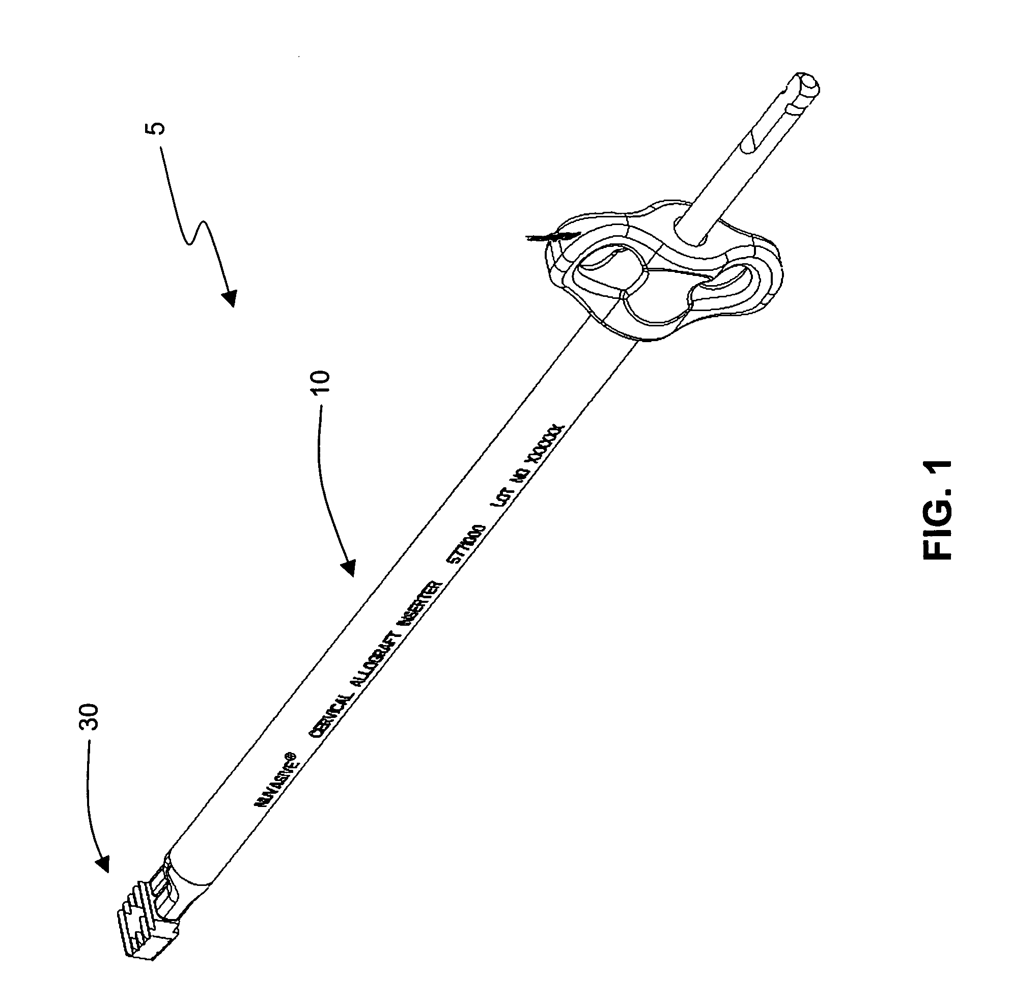
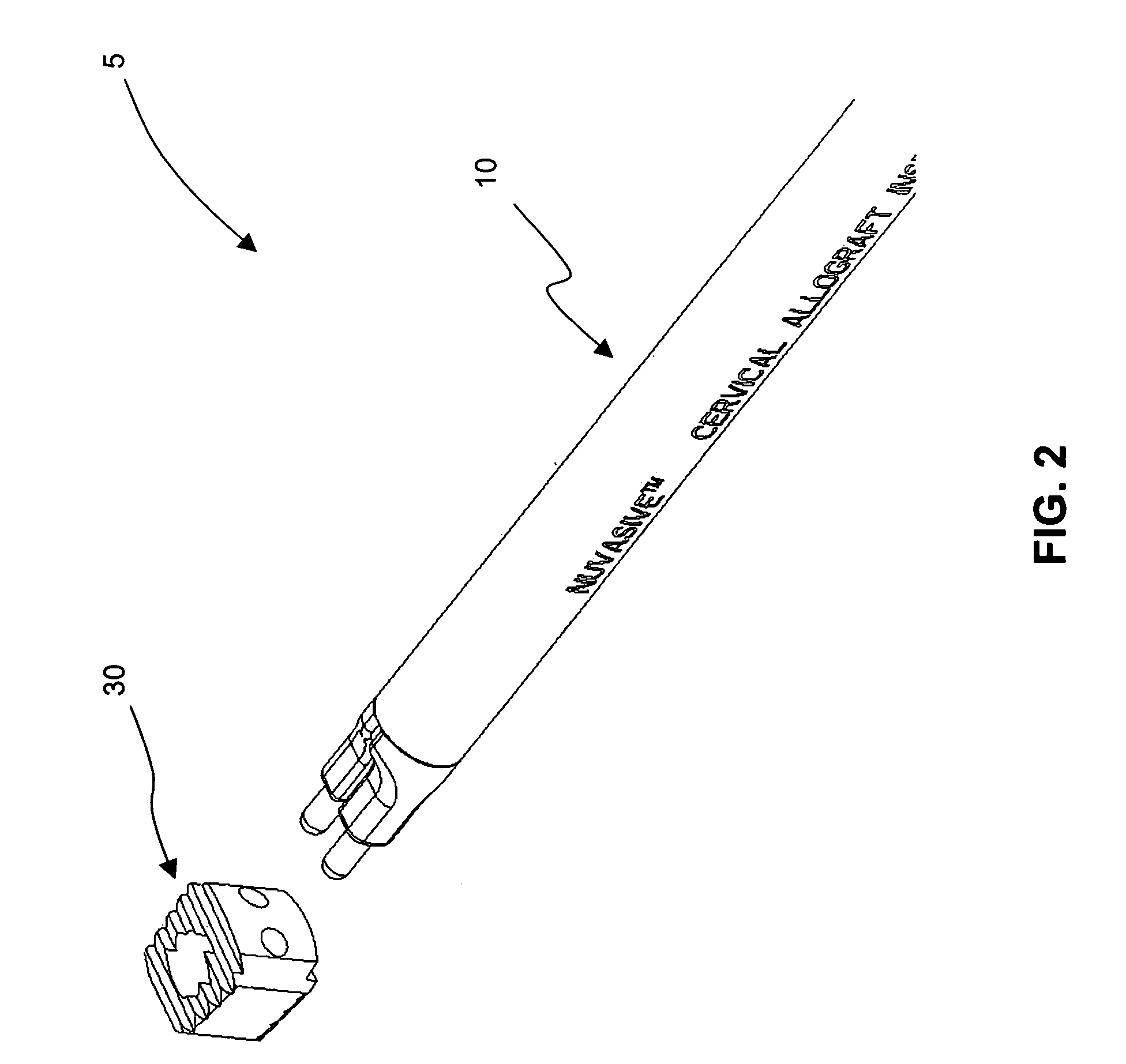
[0026]FIGS. 1–2 illustrate a system 5 for performing spinal fusion between adjacent cervical vertebrae, including an exempl...


PUM


Abstract

A system for performing spinal fusion between adjacent cervical vertebrae, including an implant and an introducer system, and related methods.

Description

CROSS-REFERENCE TO RELATED APPLICATION[0001]This application claims the benefit of the filing date under 35 USC 119(e) of provisional application entitled “Spinal Surgery Systems and Methods”, Ser. No. 60 / 336,501 filed Oct. 30, 2001, and fully incorporated herein by reference.BACKGROUND OF THE INVENTION[0002]I. Field of the Invention[0003]The present invention relates to spinal surgery and, more particularly, to systems and methods for performing spinal fusion between adjacent cervical vertebrae.[0004]II. Discussion of the Prior Art[0005]Intervertebral spinal inserts are used to provide support and maintain normal distance between adjacent vertebrae in cases where a patient's vertebral discs have degenerated. Such degeneration can occur as a result of aging or trauma and typically results in pinched or damaged nerves between or proximal to the adjacent vertebrae. Moreover, such disc degeneration causes shifting of the loading along the patient's spinal column, which in turn further ...

Claims


Application Information

Patent Timeline
Patent Type & Authority Patents(United States)
IPC IPC(8): A61B17/88A61F2/00A61F2/28A61F2/30A61F2/44A61F2/46
CPCA61F2/4455A61F2/4611A61F2002/2817A61F2002/2835A61F2002/302A61F2002/30476A61F2002/30601A61F2002/30772A61F2002/30795A61F2002/30904A61F2002/4627A61F2220/0025A61F2230/0065
Inventor HILDEBRAND, BRYAN D.MILES, PATRICKMARTINELLI, SCOTARAMBULA, JAREDCURRAN, MATTHEWKOVACH, ERICWOOLLEY, TROYCASTLEBERRY, JEFF
Owner NUVASIVE
Learn More