
Method of determining the position of a cam phaser

a technology of cam phaser and position determination, which is applied in the direction of mechanical equipment, machines/engines, basic electric elements, etc., can solve problems such as inaccuracy

Inactive Publication Date: 2005-07-12
DELPHI TECH IP LTD
View PDF3 Cites 21 Cited by
  • Summary
  • Abstract
  • Description
  • Claims
  • Application Information

AI Technical Summary

Problems solved by technology

However, inaccuracy can occur due to engine-to-engine variation, as well as mechanical and electrical variation within a given engine.

Method used


Image

  • Method of determining the position of a cam phaser
  • Method of determining the position of a cam phaser
  • Method of determining the position of a cam phaser

Examples


Embodiment Construction

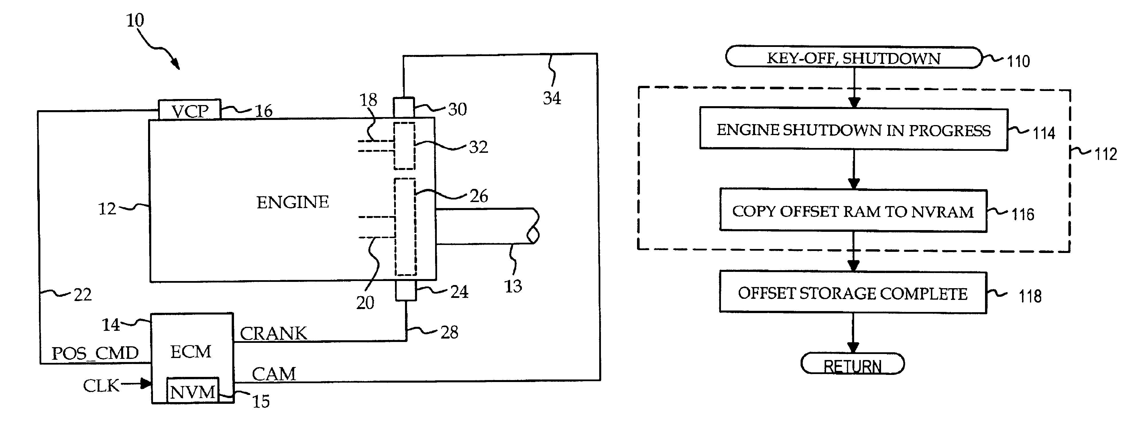
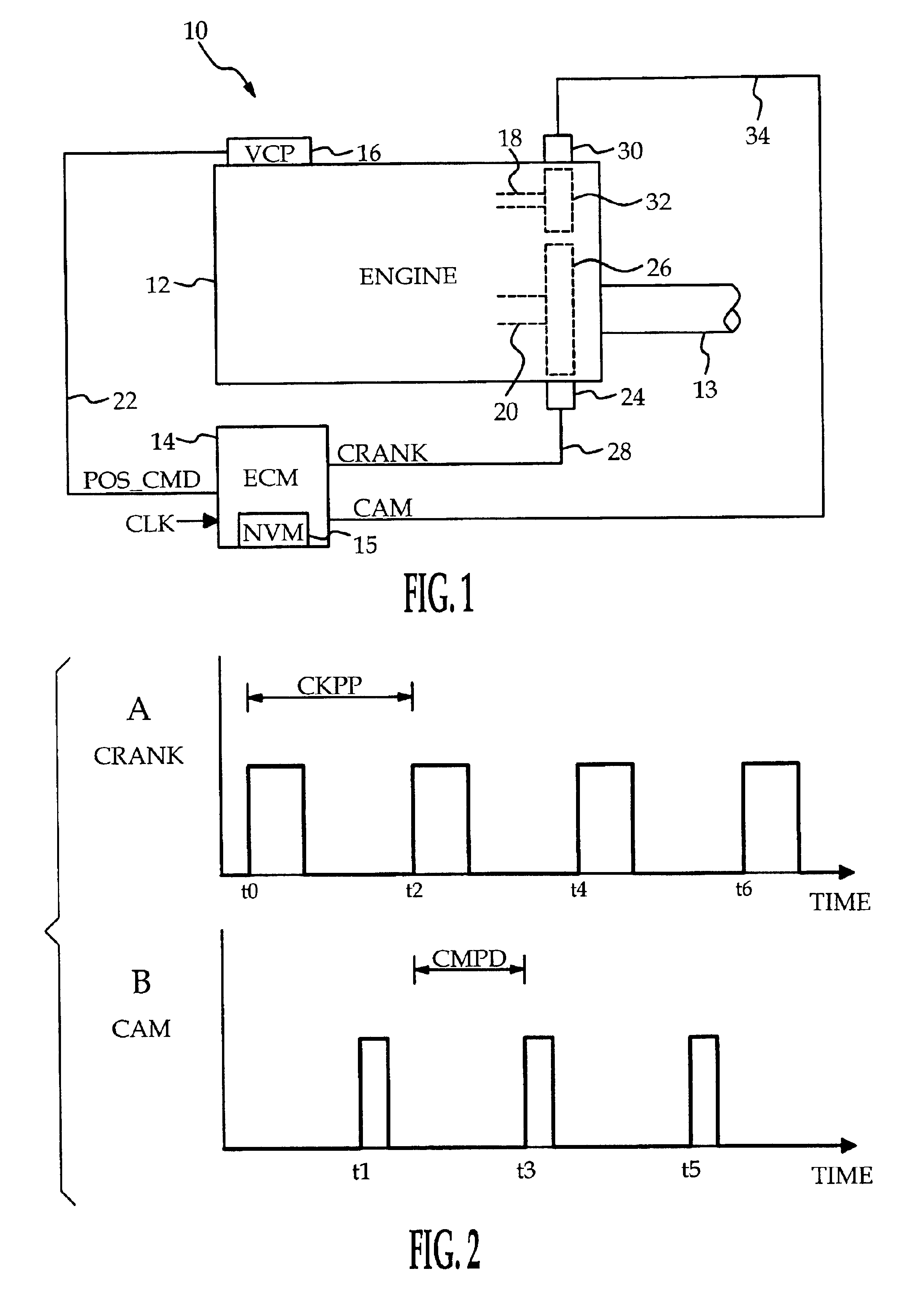
[0012]Referring to FIG. 1, the reference numeral 10 generally depicts a motor vehicle powertrain including an internal combustion engine 12 having an output shaft 13 and a microprocessor-based engine control module (ECM) 14. The engine 12 is equipped with a variable cam phaser (VCP) 16 that adjusts the phase of the camshaft 18 relative to the crankshaft 20 in response to a position command signal (POS_CMD) produced by ECM 14 on line 22. A crankshaft position sensor 24 is responsive to the passage of teeth formed on a flywheel 26 attached to crankshaft 20, and produces a CRANK signal on line 28 that includes a pulse corresponding to the passage of each flywheel tooth. Similarly, a camshaft position sensor 30 is responsive to the passage of teeth formed on a wheel 32 attached to camshaft 18, and produces a CAM signal on line 34 that includes a pulse corresponding to the passage of each tooth of wheel 32.

[0013]The ECM 14 includes a non-volatile memory (NVM) 15, and carries out a number...


PUM


Abstract

A method of determining the position of a cam phaser determines and stores an adaptively updated base offset corresponding to the phase offset of a camshaft relative to a crankshaft for a reference or default position of a cam phaser. Thereafter, the phaser position is determined relative to the base offset. Individual base offsets are preferably determined for each tooth of a toothed cam wheel, and stored in a non-volatile memory device. During engine operation, the base offsets are subject to diagnostic testing and adaptive updating, and the updated base offsets are stored in the non-volatile memory at engine shut-down.

Description

TECHNICAL FIELD[0001]The present invention is directed to the control of a phaser mechanism for a camshaft of an internal combustion engine, and more particularly to a method of determining the position of the phaser.BACKGROUND OF THE INVENTION[0002]Phaser mechanisms for continuously varying the phase of a camshaft (intake and / or exhaust) relative to the crankshaft for purposes of reducing exhaust gas emissions and improving engine performance are well known in the art of internal combustion engine controls. In general, accurate knowledge of the phaser position is essential to the achievement of accurate phase angle control. However, inaccuracy can occur due to engine-to-engine variation, as well as mechanical and electrical variation within a given engine. For example, variations in engine operating temperature can produce variations in the air gap between a toothed wheel and a speed sensor, which in turn produces variations in the sensor output. Accordingly, what is needed is a me...

Claims


Application Information

Patent Timeline
Patent Type & Authority Patents(United States)
IPC IPC(8): F01L1/34
CPCF01L1/34F01L2800/00Y10T74/2102F01L2820/041F01L2800/01
Inventor PFEIFFER, JEFFREY M.STEPIEN, GREGGGREWAL, AMANPAL S.
Owner DELPHI TECH IP LTD
Learn More