Recording tape cartridge
a technology for recording tape and cartridges, which is applied in the field of recording tape cartridges, can solve the problems of reducing the accuracy of the reel hub b>500/b> and the driven gear, the surface runout of the drive, and the flatness of the lower flang
- Summary
- Abstract
- Description
- Claims
- Application Information
AI Technical Summary
Benefits of technology
Problems solved by technology
Method used
Image

Examples
first embodiment
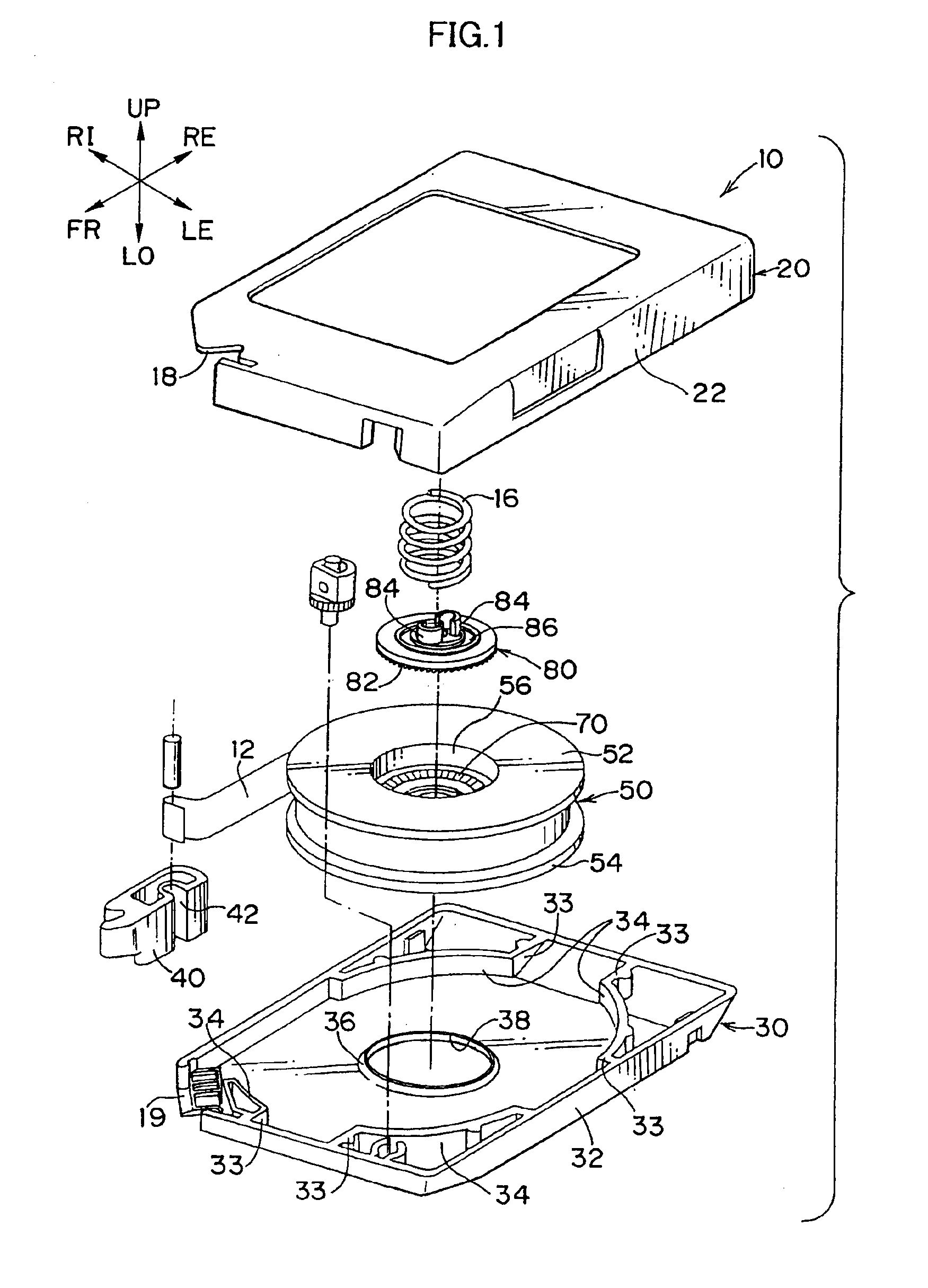
[0084]A recording tape cartridge according to the present invention will now be described. It should be noted that, for convenience of explanation, a direction in which the recording tape cartridge is mounted into a drive is referred to as a forward direction, and expressions such as front, back, right, left, upper and lower are based on this direction. Further, the recording tape used is a magnetic tape, and the following description is made with respect to a magnetic tape cartridge.
[0085]First, an outline of the magnetic tape cartridge according to the first embodiment of the present invention is described.
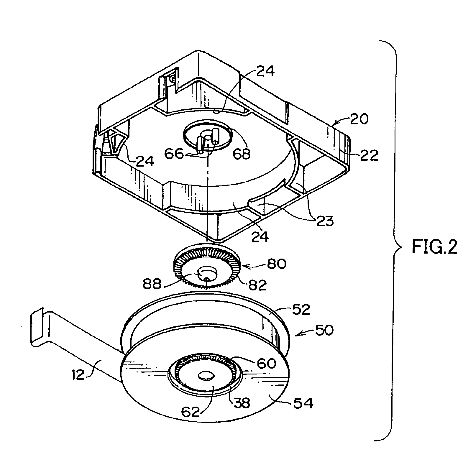
[0086]As shown in FIGS. 1-3, a magnetic tape cartridge 10 comprises an upper case 20 and a lower case 30, which are made of synthetic resin and formed in a substantially rectangular box shape. A peripheral wall 22 of the upper case 20 and a peripheral wall 32 of the lower case 30 are welded together by ultrasonic welding or the like.
[0087]Substantially cylindrical walls 24 and 3...
second embodiment
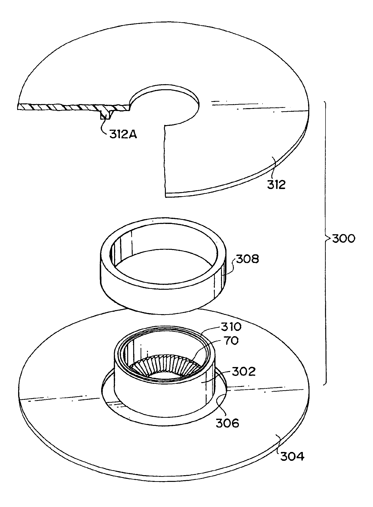
[0196]In the invention exemplified by the second embodiment, the hub and the flange are separately molded. This allows selection of a suitable gating system (e.g., disc gates) and setting of optimal molding conditions for each shape. Therefore, compared with the case in which the hub and the flange are integrally molded, variations in pressure at the hub can be reduced and flatness of the flange can be improved. Further, roundness of the hub can be improved together with the improvement in the flatness of the flange. Moreover, by welding, the hub and the flange can be united with certainty and without backlash, compared with the case in which the flange and the hub are provided with pawl portions for fitting to each other, and can be united more simply compared with the case in which the flange and the hub are threaded and screwed together.
[0197]Often in the invention, by providing a first weld boss and a second weld boss projecting from the welding surfaces, the first weld boss and...
third embodiment
[0199]In the invention exemplified by the third embodiment, the hub is placed outside the core and the recording tape is wound on the hub. Therefore, even if the core is inclined due to thermal contraction after molding of the core and the lower flange, the inclination does not affect the winding of the recording tape, and a highly accurate hub can be obtained as a result.
[0200]Often in the invention, during the thermal contraction after the molding, the thermal contraction is effected along the radial directions of the core and the lower flange. Therefore, an annular depression follows the thermal contraction of the core and the lower flange. By providing the annular depression at the lower flange on a concentric circle thereof, and fitting a sleeve of the hub in the annular depression, the axis of the sleeve is aligned with axes of the core and the lower flange. Therefore, the axis of the sleeve does not deviate with respect to the lower flange.
[0201]Often in the invention, a shou...
PUM
| Property | Measurement | Unit |
|---|---|---|
| width | aaaaa | aaaaa |
| diameter | aaaaa | aaaaa |
| pressure | aaaaa | aaaaa |
Abstract
Description
Claims
Application Information
 - R&D
- Intellectual Property
- Life Sciences
- Materials
- Tech Scout
- Unparalleled Data Quality
- Higher Quality Content
- 60% Fewer Hallucinations
Browse by: Latest US Patents, China's latest patents, Technical Efficacy Thesaurus, Application Domain, Technology Topic, Popular Technical Reports.
© 2025 PatSnap. All rights reserved.Legal|Privacy policy|Modern Slavery Act Transparency Statement|Sitemap|About US| Contact US: help@patsnap.com